II – External Parts Disassembly
- Preparation
- Remove Turbo Outlet Pipe
- Loosen Turbo Muffler Elbow
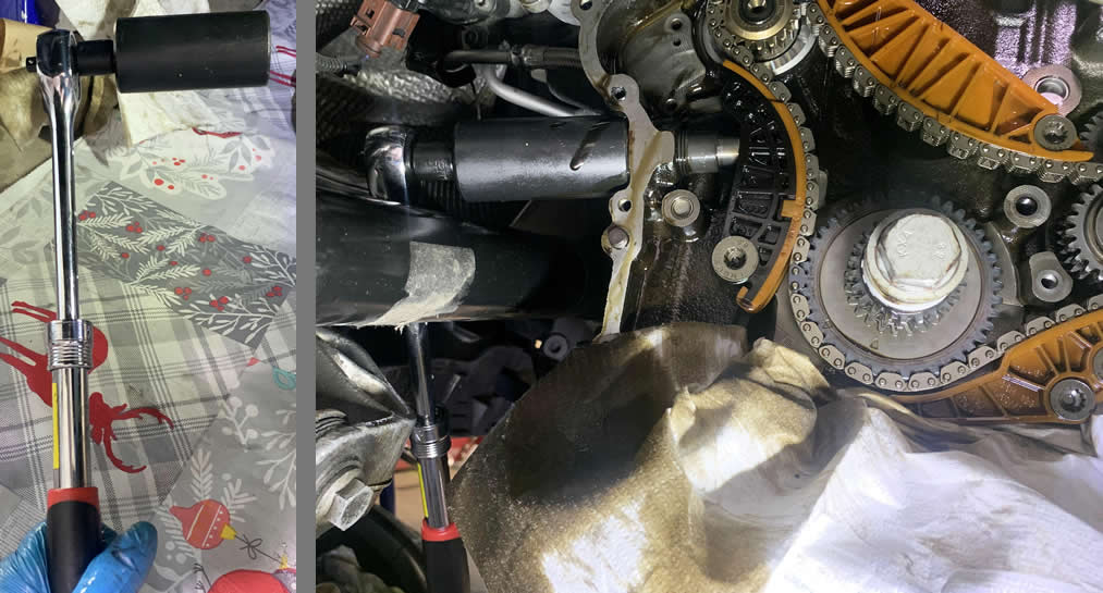
- Visual check Timing Chain Tensioner
- Remove Coolant Reservoir & Breather Hose
- Remove Coil Packs & Spark Plugs
- Loosen the Oil Dipstick Housing
- Remove Serpentine Belt & Belt Tensioner Pulley
- Remove Engine Mount
- Remove N75 Valve & Oil Dipstick
- Remove the Camshaft Adjuster Magnet
- Remove the Upper Timing Chain Cover
- Set the crank roller to TDC
III – Timing Chain Components Disassembly
- Remove the Crankshaft Roller and the Lower Timing Chain Cover
- Remove Oil Pump Chain Tensioner
- Remove the Camshaft Bridge
- Remove Upper Timing Chain tensioner
- Remove Upper Timing Chain Guides
- Remove Lower Timing Chain Components
- Replace the Crankshaft Sprocket
IV – MK6 Timing Chain Replacement
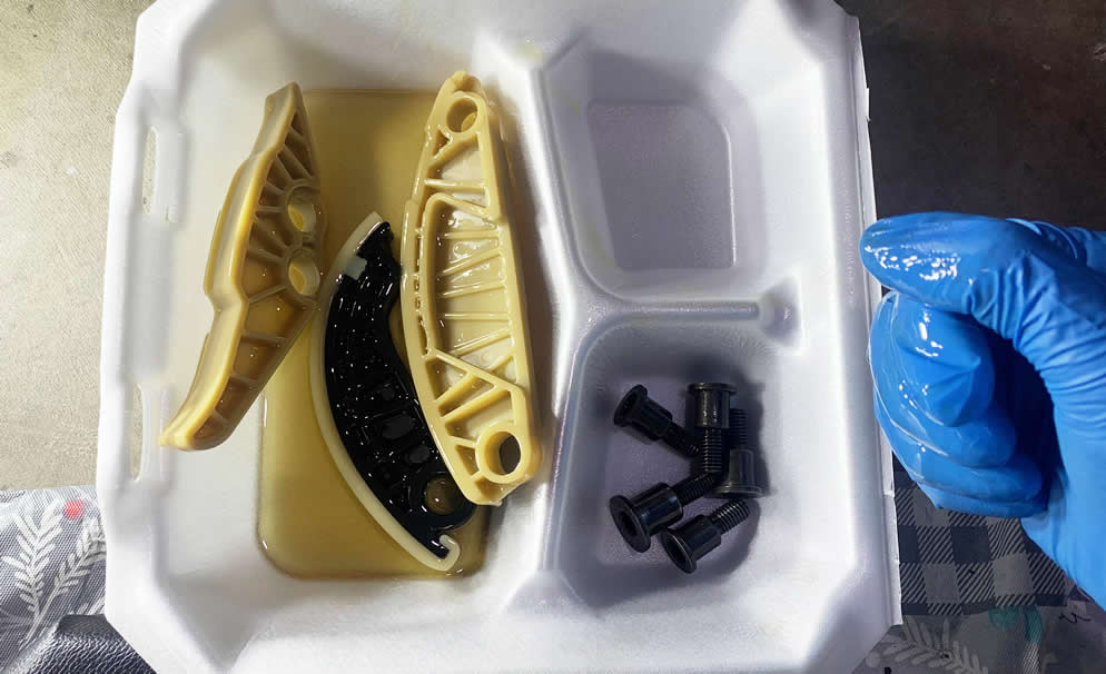
- Soaking the New Chains and Lower Tensioner
- Set up Lower Timing Chain and Guides
- Set up Upper Timing Chain and Guides
- Install Timing Chain Tensioners
- Reinstall the top Guide and Cambridge
- Closing up Timing Chain Compartments
- Install the new Crankshaft Bolt, the Serpentine Belt and Oil Dipstick Housing
- Reinstall Engine Mount
But here is my fair warning, fixing the MK6 TSI 2.0L timing chain issue is an absolute one hell of a job –and naturally it requires a hefty list of tools, bunch of parts, bunch of time, a dozen of thoughts and prayers along with a lot of patience. They don’t just charge $1200 (tensioner only) ~ $3,800 (timing chain assembly) at the stealership and behind it for no reason. This article was written in the past so those of us living in today future, I bet your economy will see an even higher price tag.
So with that being said, I’ll do my best to simplify this complex repair job as practically as possible and I hope you will see that throughout the article. My goal? Help you save some money and gain some proud pro experience. If you have suggestions or find anything confusing / missing, let me know in the comment section or on our VW EOS group and I’ll get to it.
Anyway, I shall categorize the parts and equipment that you should need into two section, Essentials and Optionals –one you should really own to get through all the works smoothly and successfully while the others would be great to have but who knows. I own every piece in this list so you can rest assured that I’m not recommending some unnecessary bullshit. At the end of the day, the big challenge from this repair isn’t technical difficulty but a lot has to do with impatience and frustration. If things get hard, take a longer break and come back fresh to tackle the problem.
A. Essential Items for TSI 2.0L Timing Chain Replacement


B. Optional Equipments, Hardware and Upgrades
OPTIONAL TOOLS |
|
| Loctite Blue | |
| Creeper Pad | |
| Secondary Floor Jack or existing Emergency Roadside Crossjack | |
| Liqui Moly MOS2 Anti-friction Engine Treatment *I use this to soak new chains, but if you want to use engine oil it’s fine too. |
|
| Cordless Impact Wrench *Mainly used to take off lug nuts and crankshaft bolt. |
|
| Bright LED Lighting Kit | |
| Impact Socket Set | |
| VW Purple Coolant Concentrated *You may lose some coolant during the disassembly process, it’s recommended to have this in case you need a top-off. |
OPTIONAL HARDWARE / UPGRADES |
| Any bolts and o-rings listed here can be reused from the orignals, unless they are damaged. Then you can come back to this and know what to find. | |
| Upper Timing Chain Cover Gasket + Front Seal (06H103483C) | |
| Cambridge inner o-ring WHT007212B | |
| Cambridge 06H103144K (include inner o-ring WHT007212B) | |
| 6x Cambridge Torx Bolts N10470703 | |
| 2x Torx bolts (N10554005) for Upper Timing chain tesioner | |
| N205 Solenoid Vale 06H109257C | |
| Turbo Muffler Delete kit | |
| Street Density Motor/Trans Mount Kit | |
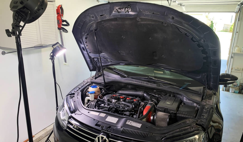
An important aspect that we often overlooked is decent lighting at the repair site. Take your time to set up a clean and bright work area so you can avoid frustration down the road. I learned the hard way when my eye-fatigue quickly led to a major mistake where I totally regret two seconds later.
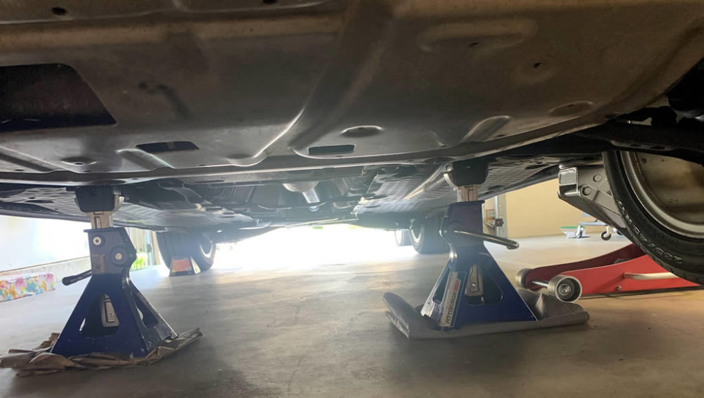
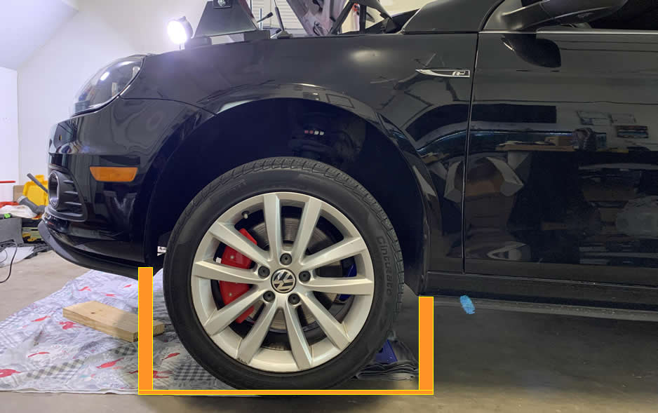
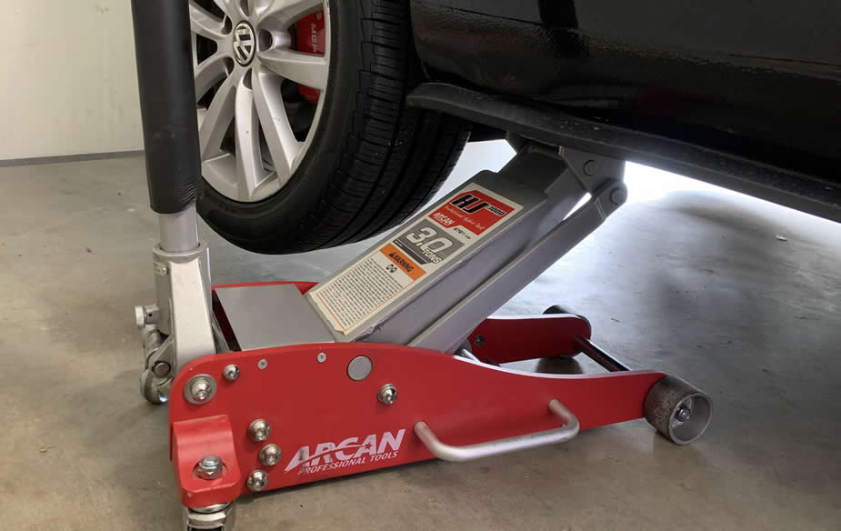
Another significant precaution you must take is jacking the car up properly for this particular job.
This is quite vital for your safety as well as to avoid unexpected expenses. Your interactions with the engine during this repair requires pulling, pushing, jerking stuffs from the top to the bottom of engine block, sometimes with great force. You need a strong support so you don’t find your engine sitting on the floor after break, or it funnily falls on you while you are under and then you wake up dead.
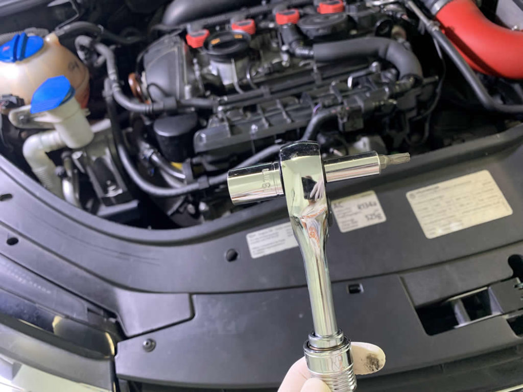
Once you got that down, time to take out a T15 Torx and 13mm wrench socket. I happened to have this dual-head ratchet so it saved me a bit of time.
Go ahead and remove the undercarriage Splash Shield (1Q0825237B for the EOS).
While you are under, move on to the passenger side fender liner. Remove these bolts:
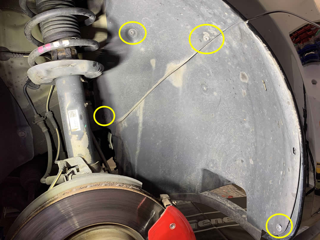
There are two more at the bottom.
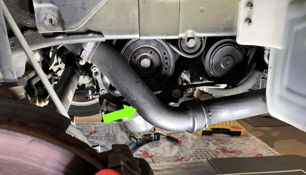
With the fender liner removed, you’ll have access to the Turbo Outlet Pipe and its coupling hoses. Yours might look at little different to mine, but the removal process will be practically similar.
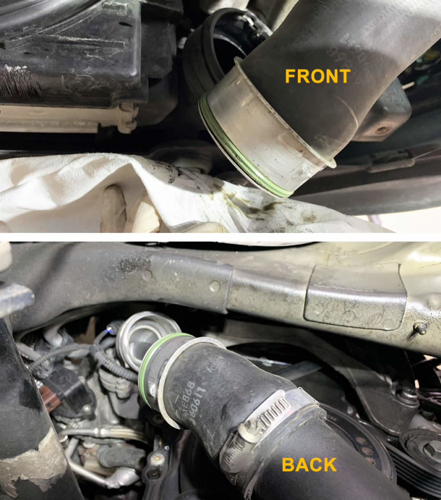
On the far up left side of the pipe (back), there is an U-shape bracket with notch that you can stick a flat screwdriver in and pry it off.
You’ll see the same bracket again towards the front of the car.
I’m not sure if this is just me, but my two brackets are not the same size. The front one is slightly larger than the back.
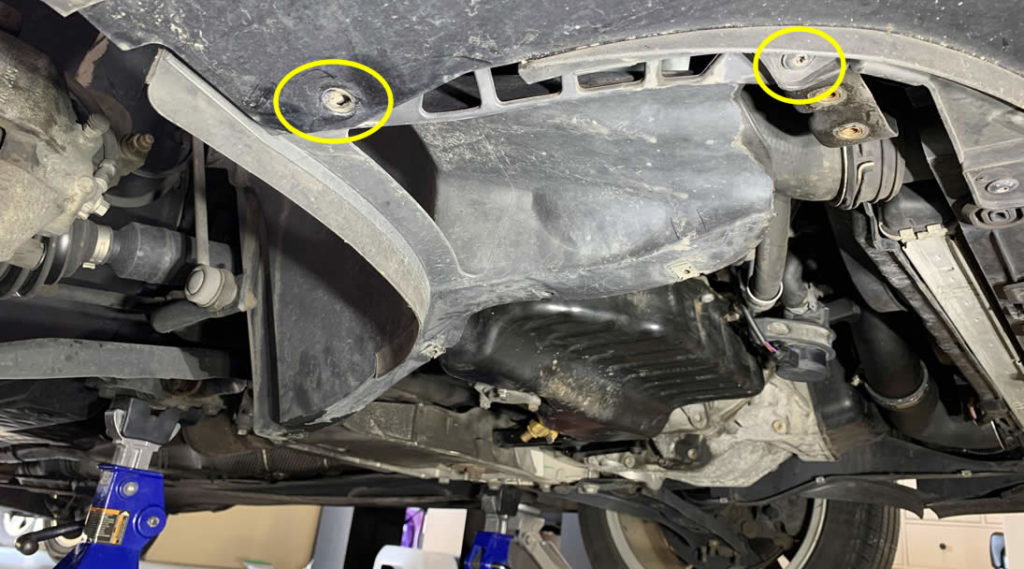
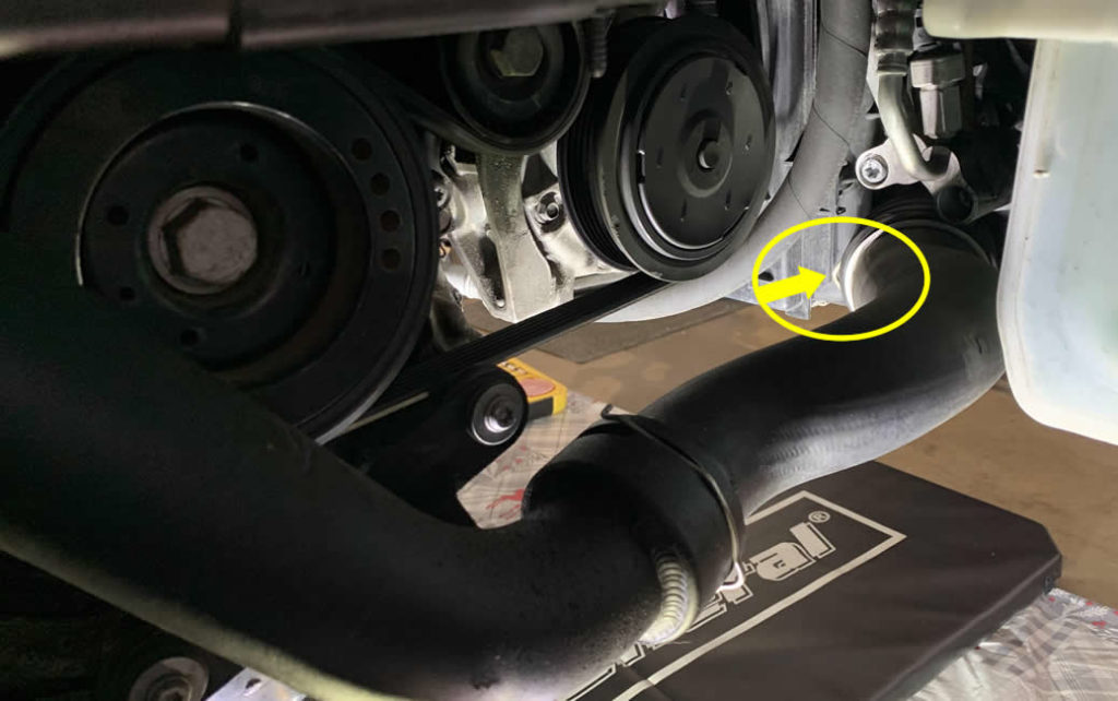
Now back to the center of the pipe, you can go ahead and remove these two bolts to separate the pipe itself from the engine block.
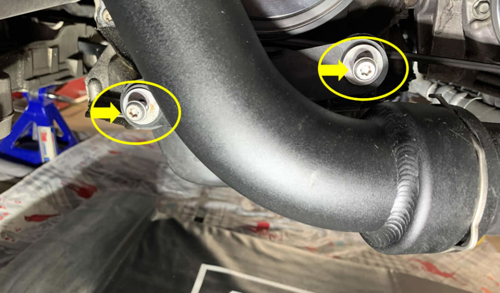
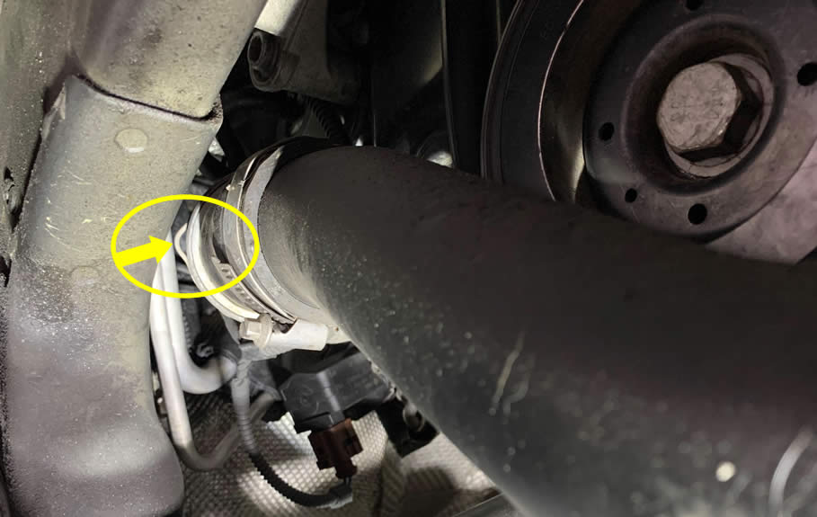
Slowly turn each of the coupling hoses to disconnect the entire Turbo Outlet pipe assembly.
When the Turbo Outlet pipe is out of the way, you could remove this little bracket as well.
Removing the Turbo Outlet hose will reveal the Turbo Muffler, sometimes known as the Turbo Elbow. There is a connector behind the turn, so you might need an angle pick tool to disconnect it due to extremely small space.
There are 3 bolts securing the Turbo Muffler to the block and you can use a variety of tools such as small flex head ratchet + extension with H5 Allen Hex bit attachment to remove them.
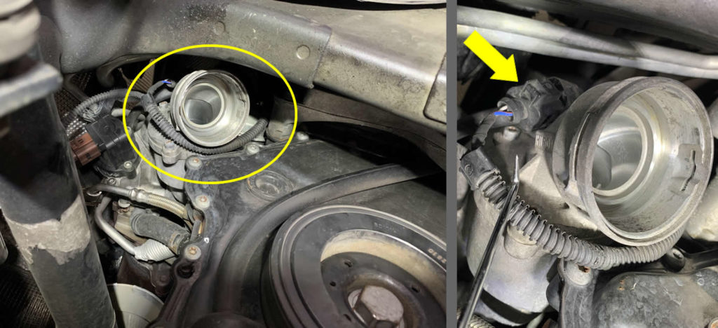
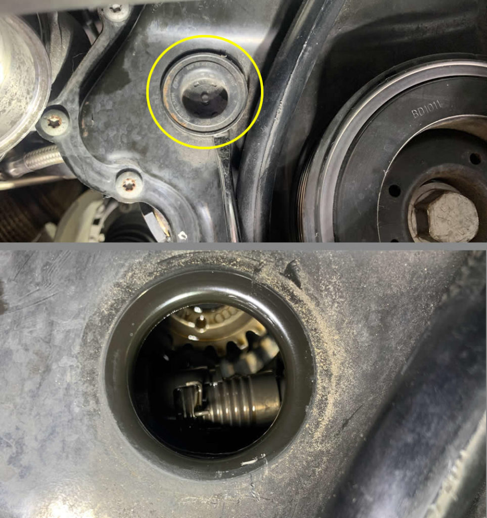
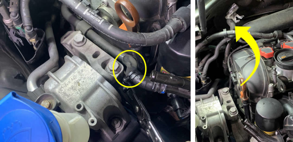
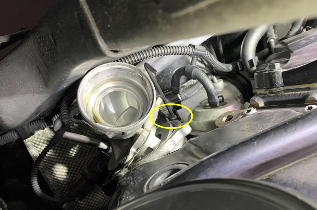
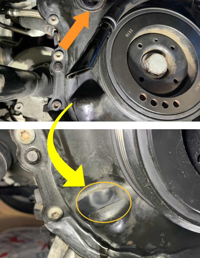
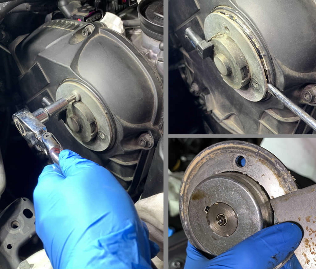
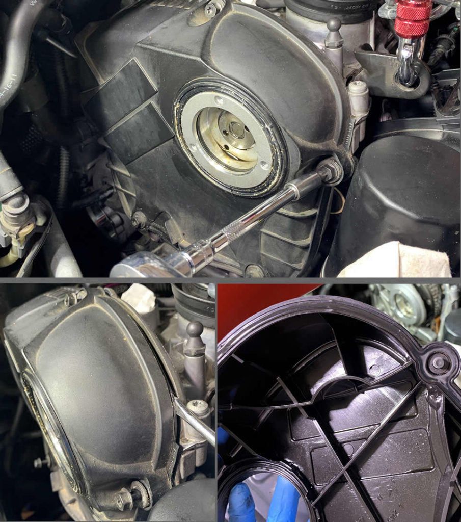
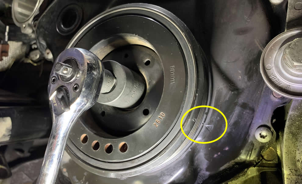
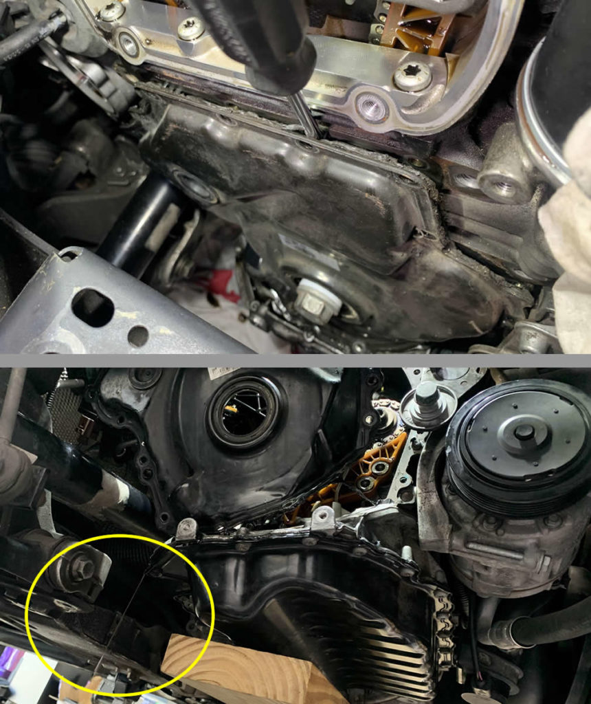
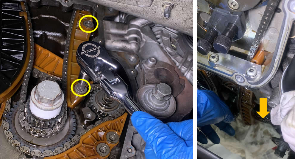
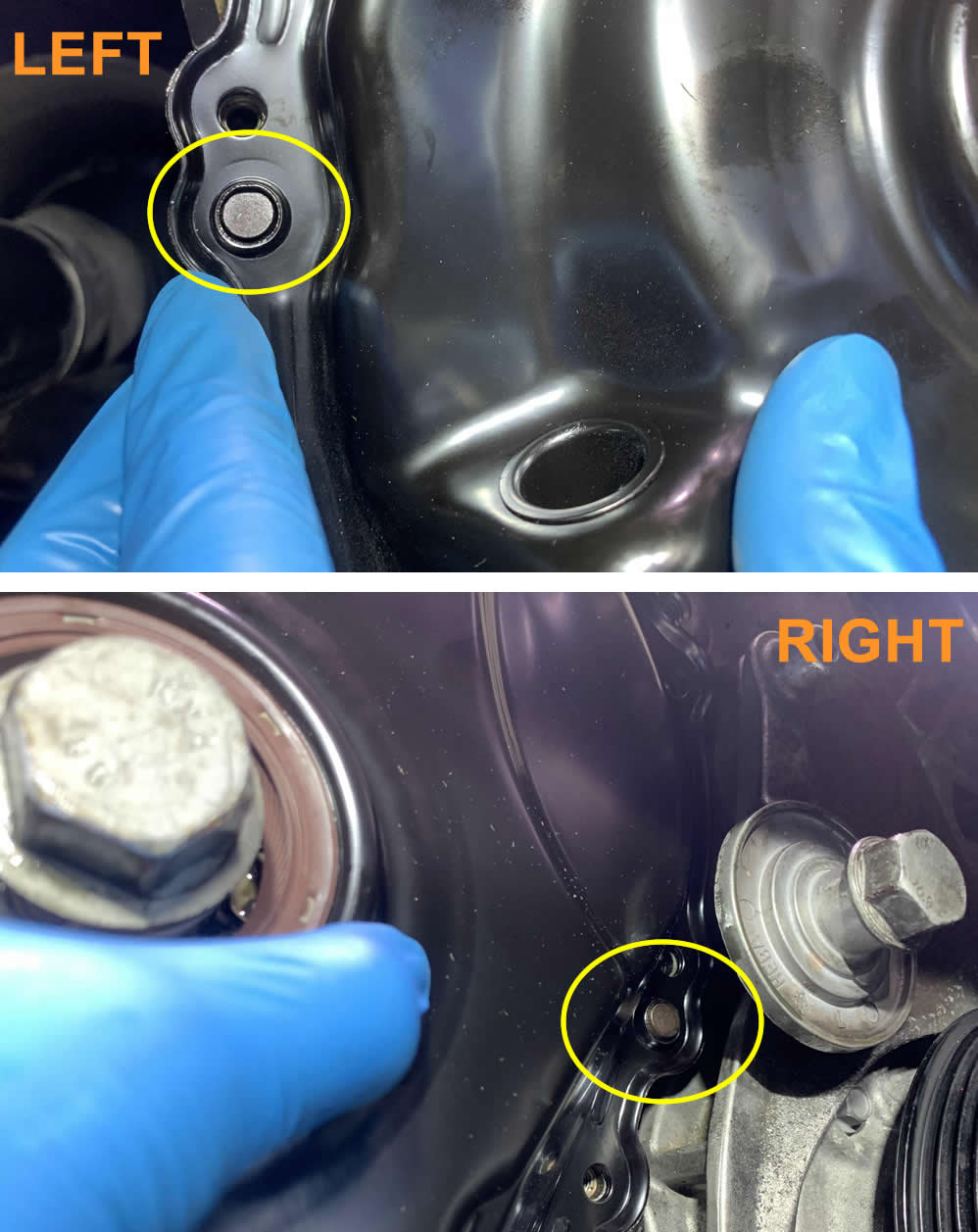
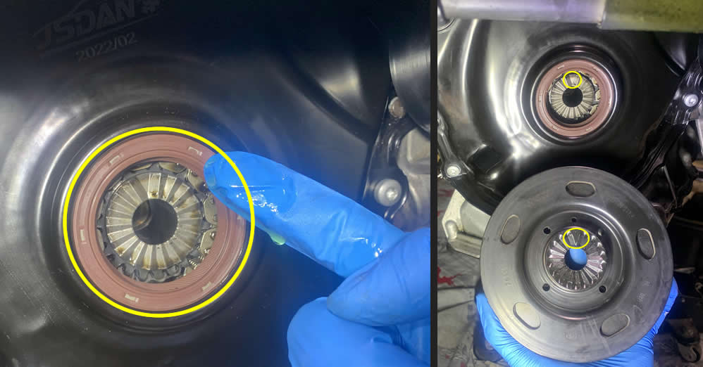
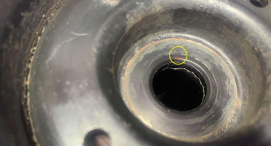
After you took off the Turbo Outlet pipe, you should be able to locate this little cap on the black cover right behind it. Pry it off with a flat screwdrive to open a peek hole to many nightmares.
If yours look something like the photo, you can sleep better at night now because you have the newer revision. If there is no groove and it’s all smooth, you have an older version.
Now moving on to the top of the engine bay. First, let’s take it easy by disconnecting the Breather hose (1K0133366BP) from the engine.
- Squeeze the latch to remove the hose from its retaining clip.
- Use a hose clamp tool to slide the clamp further back, then use a pick tool to disconnect the hose.
Tuck it somewhere out of the way.
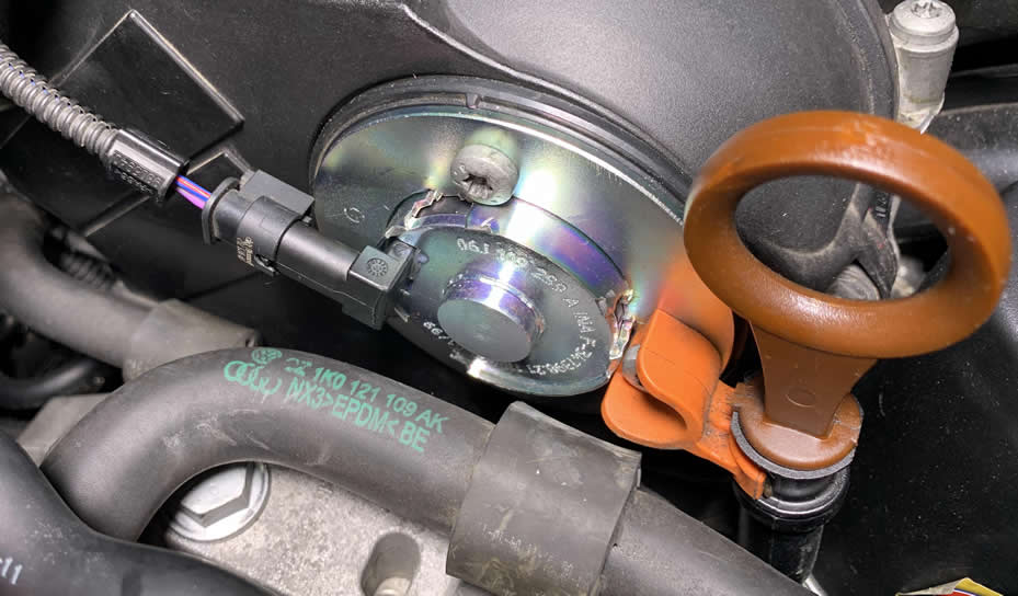
On the passenger side of the engine, you will see two coolant hoses on top of each other. Disconnect the top Reservoir hose first (1K0121109AK) and drain it into a pan underneath.
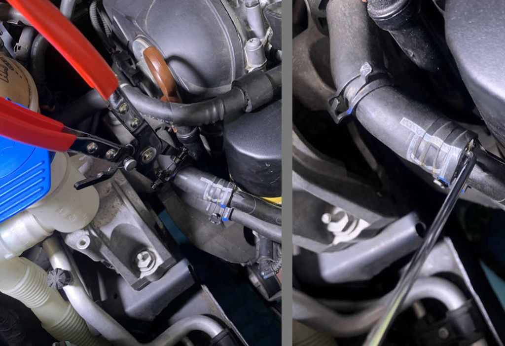
While waiting for the coolant to drain, you can go ahead and disconnect the coolant return hose and the coolant level sensor.
![]()
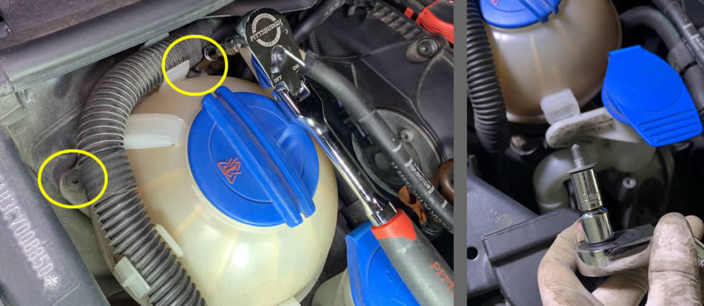
The coolant reservoir is held in place by two T15 Torx screws and one 10mm bolt.
After you took the coolant reservoir out, you can continue to disconnect the lower coolant supply hose. To avoid confusion with the Reservoir hose earlier, this bottom one has sleeve. There will be more liquid coming out, be prepared!
I also decided to cover the open end of the hose with a plastic wrap and tuck it near the firewall.
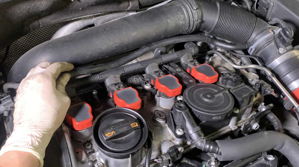
Press the tab on the connector to raise up the latch, then you can pull the connector back from the ignition coil. A pick tool again will make this task effortless.
After that, you will find resistance when removing the ignition coil itself from the engine. Wiggle it 1⁄8 of a turn to left and right while simultaneously apply an upward pulling pressure will help you get them out in a short time.
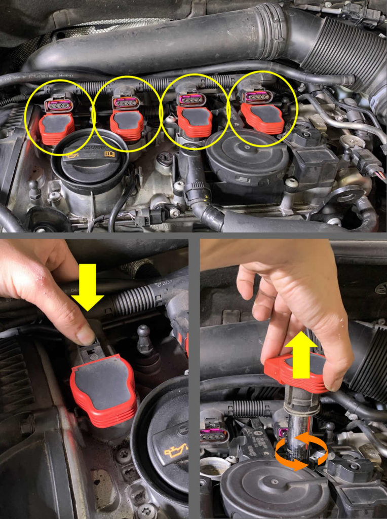
Each coil pack removed leaves you access to the spark plugs. It’s optional to remove these little guys but I highly recommend you do so. It’s easier to crank the engine without tension from the spark plugs, and you will be glad you have them removed now.
![]()
There are two bolts attach the oil dipstick housing to the engine block. You can use a T30 Torx to remove them.
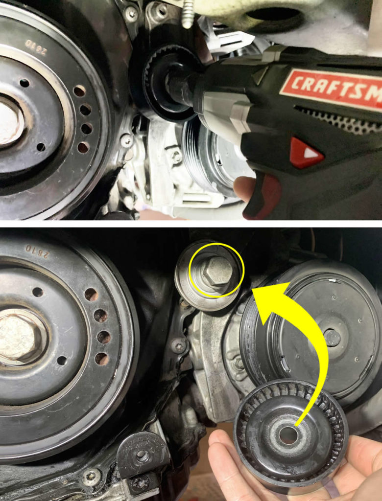
I use this kit from Harbor Freight (Amazon also has it) to rotate the Serpentine Belt Tensioner and release tension on the belt in order to remove it. You will need a 17mm impact socket to turn the nut.
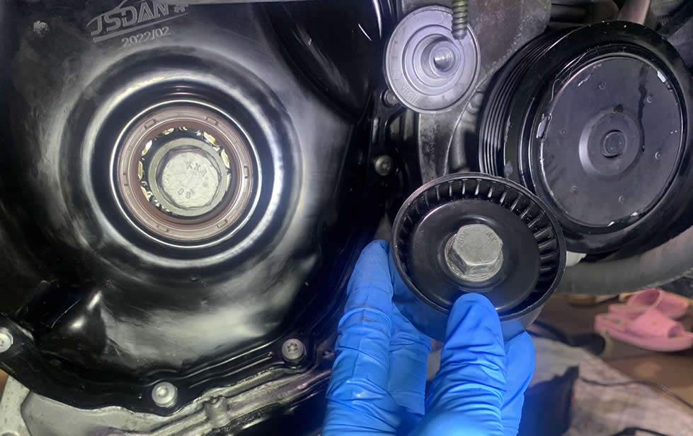
Once the belt is off, you will have to remove the pulley from the belt tensioner itself. This gives room to reach the cover bolt behind it later.
- Use a torque wrench or a breaker bar equipped with the same 17mm impact socket you used earlier to remove this bolt. When the pulley is out, put the bolt back on and just hand-tighten it.
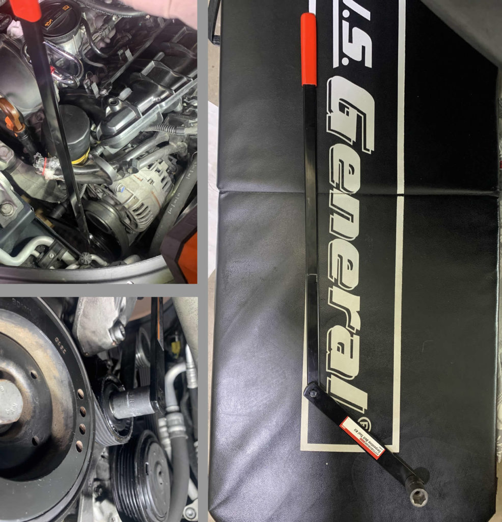
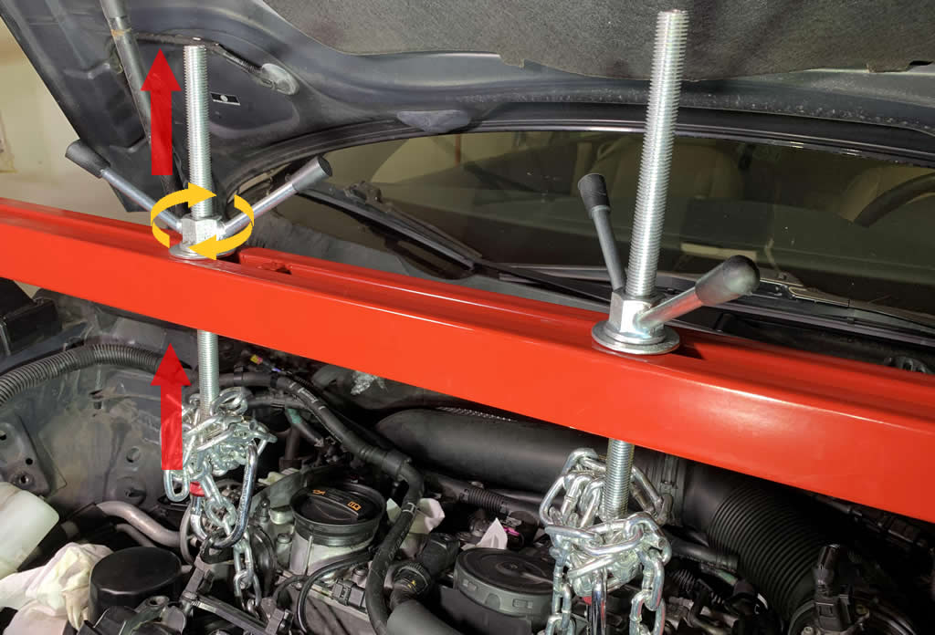
As you take off the engine mount, there will be nothing in place to secure the engine to the frame. Thus we need a good support system to prevent unnecessary mechanical and medical expenses. I use the engine support bar to keep the engine as stable as it could be while we work on the timing chain later.
That being said, I have a spare floorjack and a 2×4 laying around so I might as well use them as a secondary support system in case the bar fails for some reason. Utilize the emergency crossjack from the trunk if you don’t have a second floorjack or you can relocate the first floorjack for this purpose.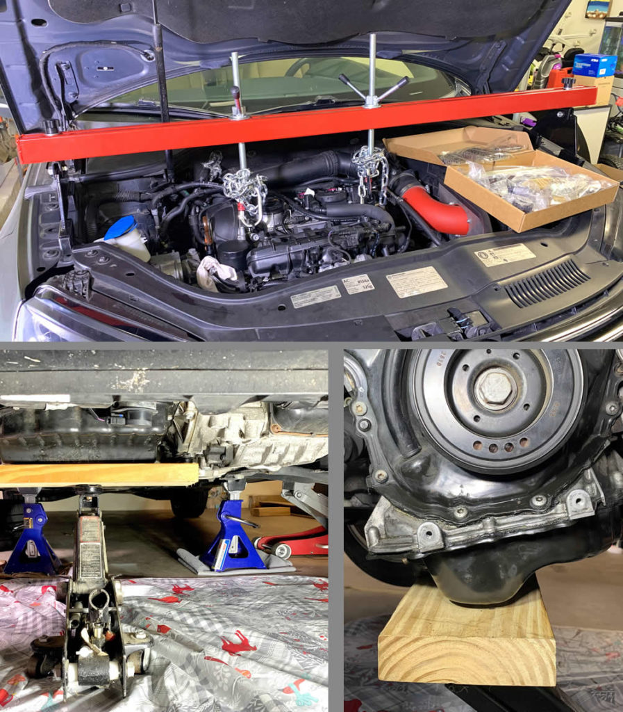
The setup for the support bar is basically using the included chains and equipment themselves along with a pair of rock climbing carabiners rated 5000lbs to connect to the engine lift brackets. Then you turn the wing nuts right above the red bar just enough to keep the engine in place exactly where it currently is.
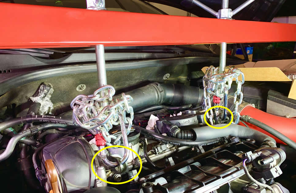
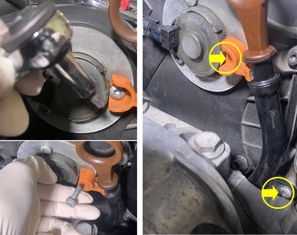
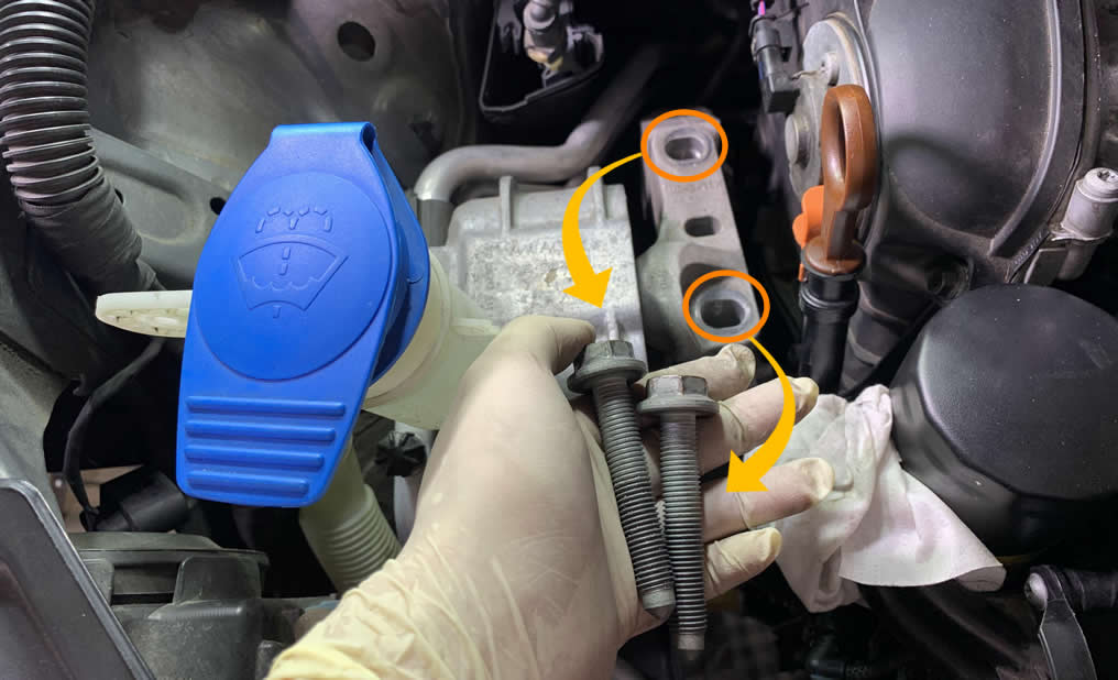
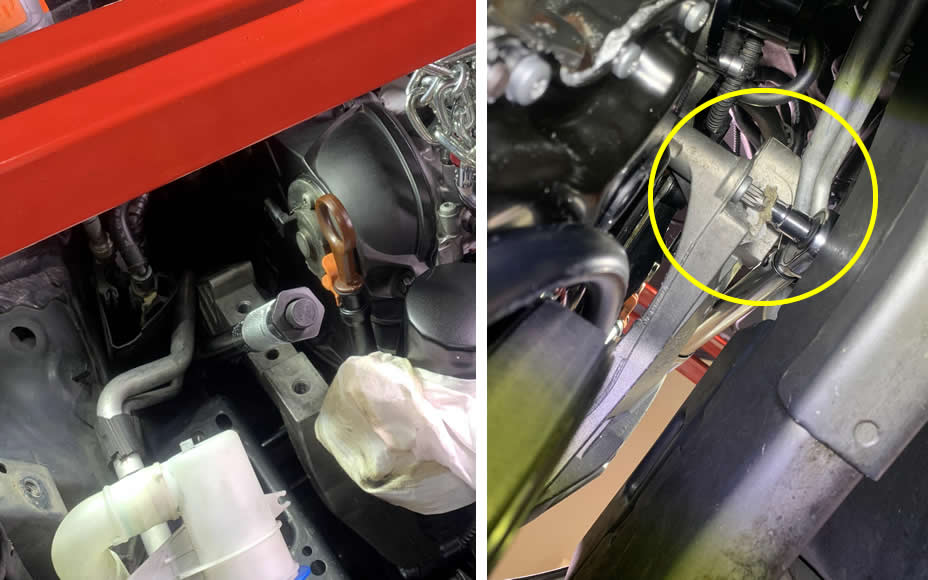
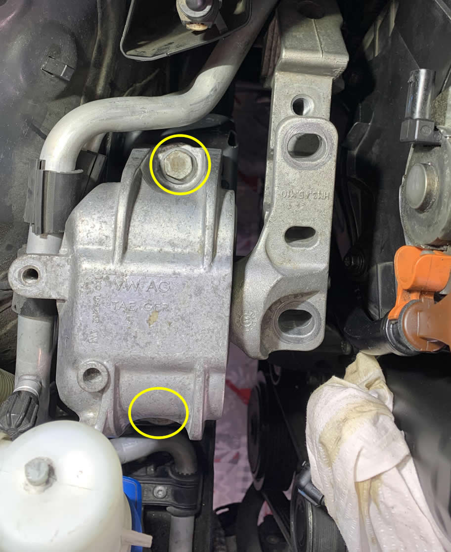
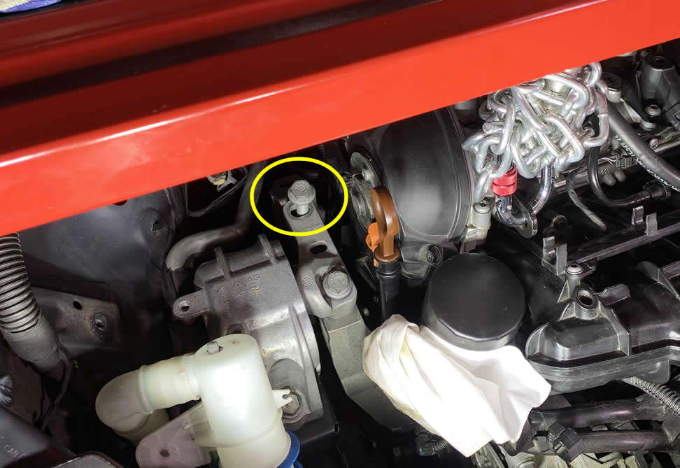
Proceed to remove this bracket that holds the windshield wiper fluid refill cap (yellow circles below). Then you start remove the bolts that attach the engine mount to the body mount (orange). These stretch bolts were torqued to over 50 ft-lbs so they will require some Mana for removal.
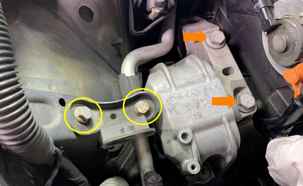
Take out those two TTY bolts (N10552402) from the mounting bracket. These are stretch bolts and they are a one-time use. You must replace these bolts each time you remove them since they lose the grip strength significantly if reused.
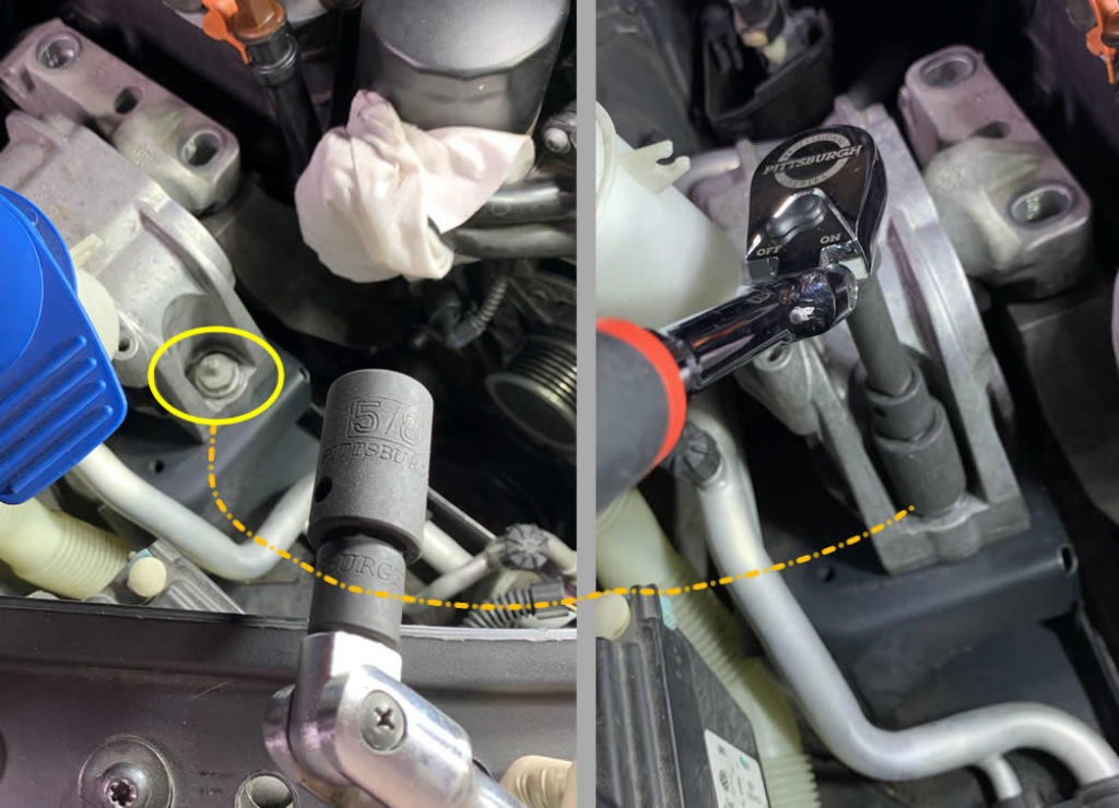
There is this weird TTY stud bolt that you might need a deep impact socket to remove. You can attach socket to a flex ratchet or a breaker bar to set it loose because these engine mount bolts tend to be very stubborn. Fortunately, the bolt on the other side is just a normal flat top hex.
These are the bolts (N90596906 and N91029602) taken out of that engine mount body bracket. Lift up the mount and inspect for any wear or tear. Mine ripped a little near the top here so I ordered a set of performance motor and tranmission mounts for replacement.
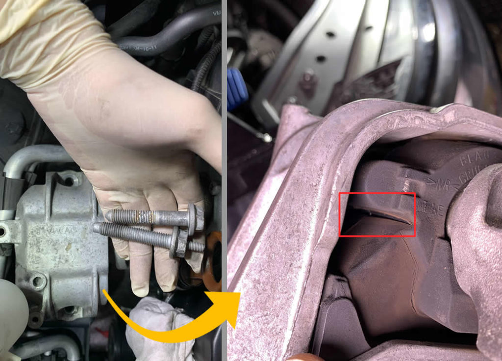
You’re half way through to remove the engine mount assembly.
As you probably realize now, the engine mount assembly is consisted of two parts. One bracket attaches to the frame and the other to the engine block. They both connect together via strong TTY bolts. So you got the first part out, now onto the second.
This is pretty tricky and is the reason many people gave up. But bear with me and we can get through it in no time. I give it a year and a half.
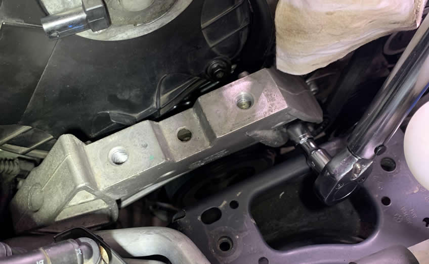
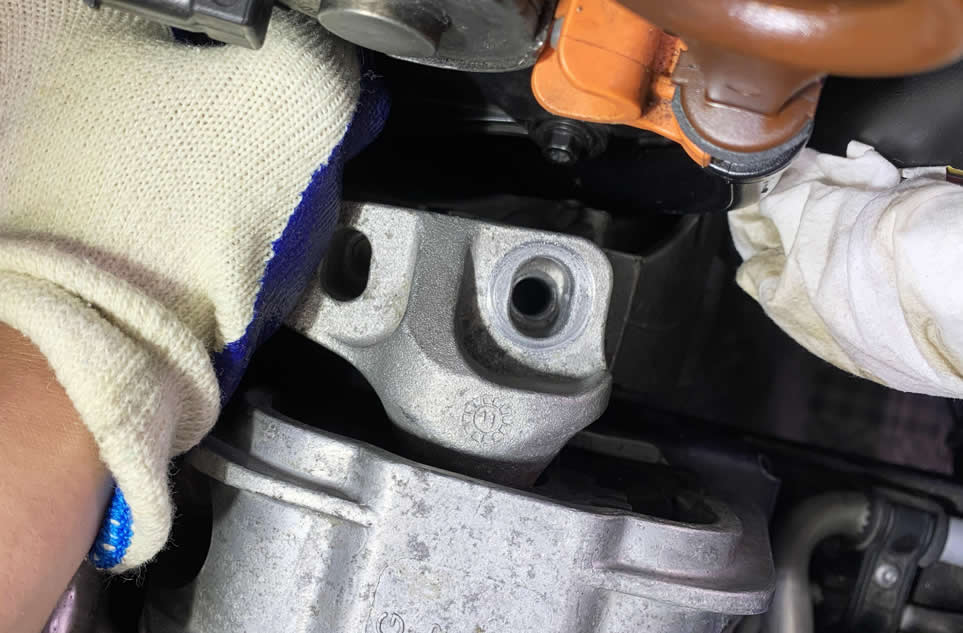
Let’s first have a visual understanding of how this mount bracket looks like.
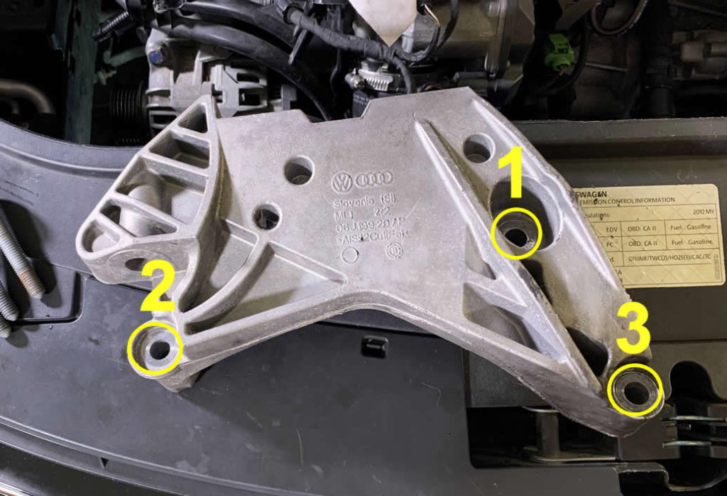
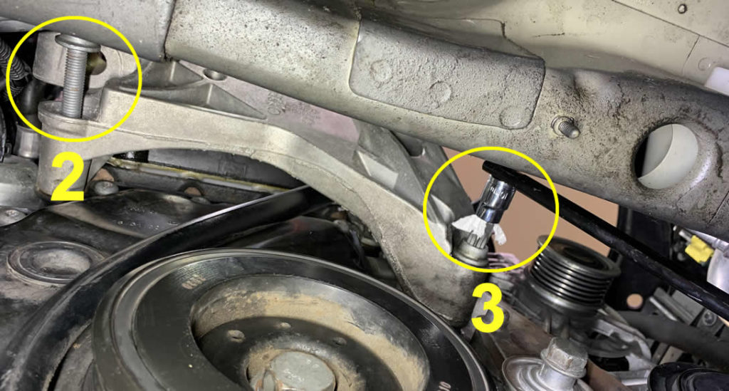
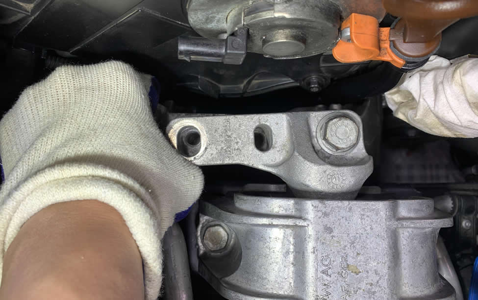
This mounting bracket is facing the frame and unfortunately there is almost no room for you to get a tool in there to reach those 3 bolt locations. In order to tackle bolt #1 and #2, low-profile is key and this is also what you need:
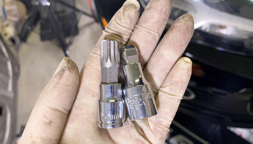
- Short Triple Square M12 bit attached to a 3⁄8 10mm socket.
- A short socket extension.
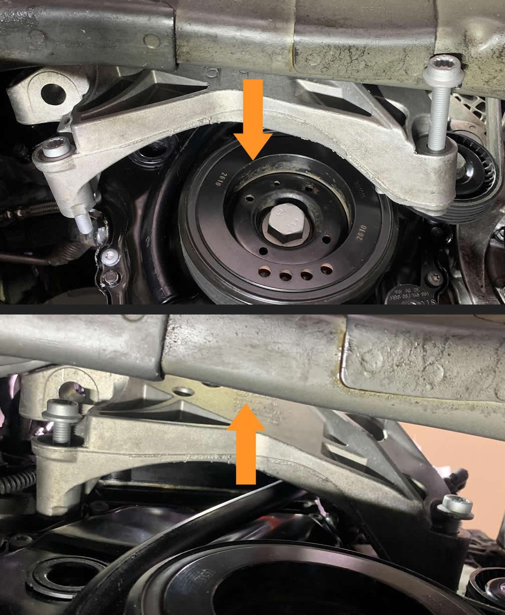
Now from the top engine bay, you need to raise you engine side a little higher. Anywhere between 1″ to 2″ using the support bar. Turn the wing nut slowly and gradually clock-wise until you can reach the first bolt through the frame.
Turn the wing nut slowly and gradually clock-wise until you can reach the first bolt through the opening on the subframe…
Or above it.
You should also be able to break off the #2 bolt all the way as well. In some case, you might not be able to get it out at first due to its head hitting the frame. But everything will come off when you loosen the third bolt.
Now you can drop the engine lower, and go under to remove both the second and the third bolt. I find using the thin bar from the Harbor Freight Serpentine Belt toolkit (also available on Amazon) worked wonderful. Time to take that damn mounting bracket out.
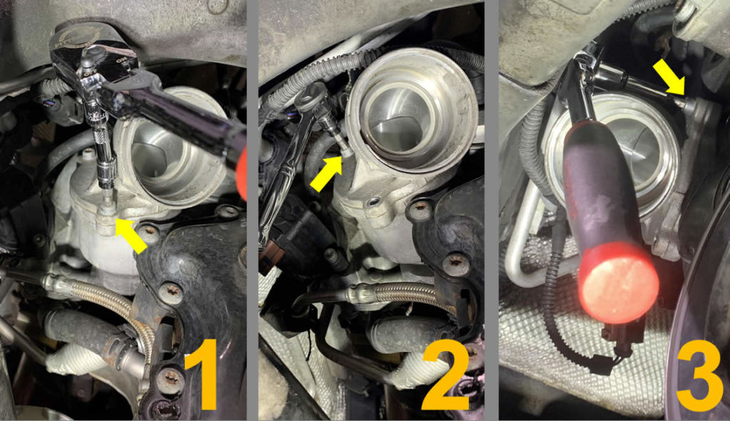
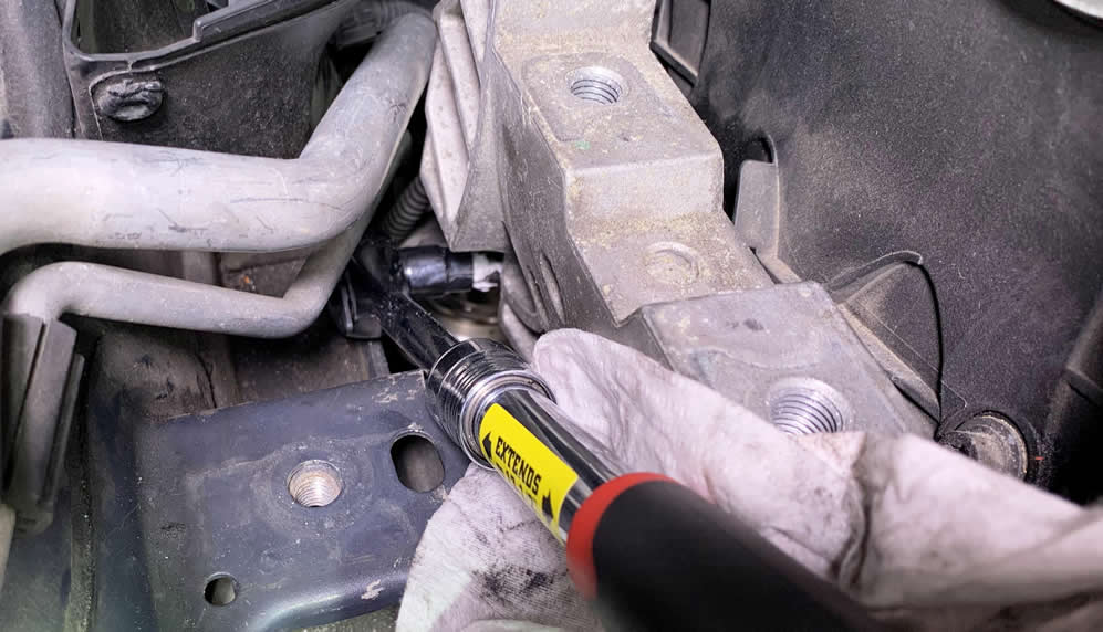
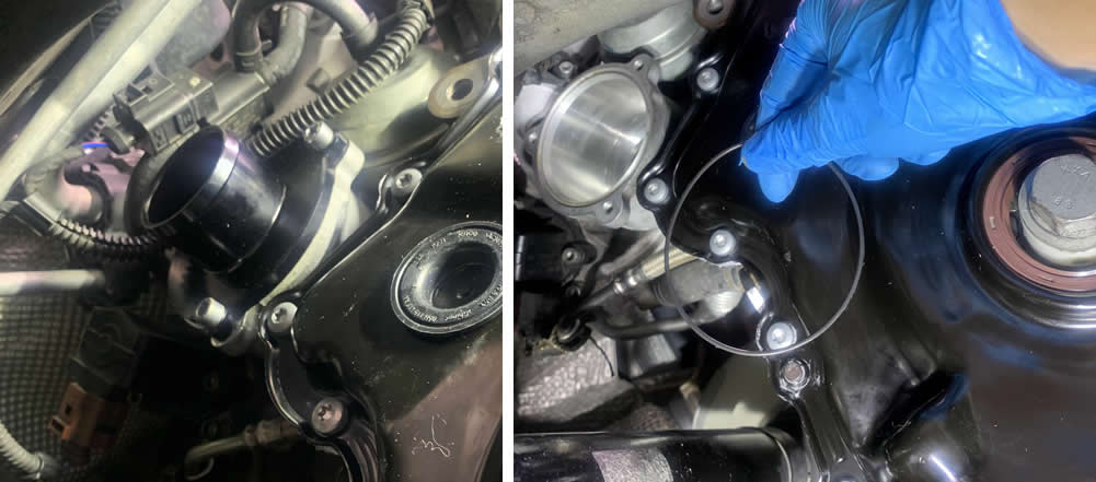
Remember when you could not get the Turbo Muffler elbow earlier off due to a connector blocking the way? Now is the time for you to tackle this task with a long arm size-4 Hex key.
There two bolts on each side of the valve and I’m sorry if you have big hands. This is very challenging time indeed. But at least you can move the Turbo Muffler around to find room, take full advantage of that luxury.
While you are still around this part of the wood, you can also go ahead and gently yank the oil dipstick housing out of the oil pan. The only resistance there is, is from the o-ring itself so be very mindful. Namaste. And put a tape over the opening to prevent objects falling in the oil pan.
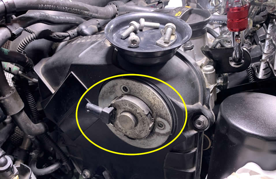
After you removed the dipstick housing component, you can continue to remove the Camshaft Adjuster Magnet (06J109259A). It’s held by two more T30 Torx bolt. If it looks disgusting as mine then you might want to give it a good scrap and wipe off the excess so when you reinstall it later, it will sit tight with the inner o-ring.
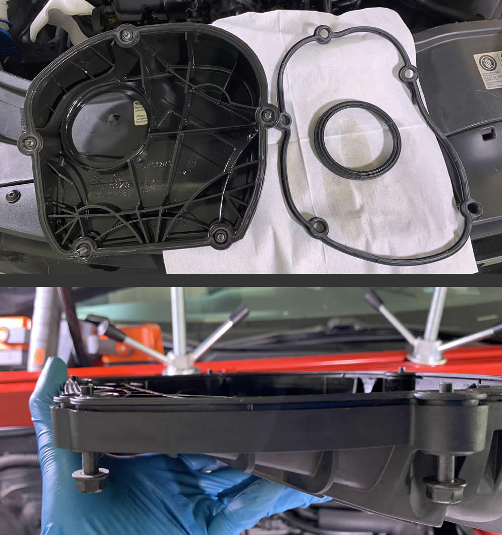
Continue on to remove the black top cover (06H103269H) to reveal the upper timing chain components and all their glory. This is a good time to inspect the rubber gasket / front seal and order new ones (06H103483C) if needed.
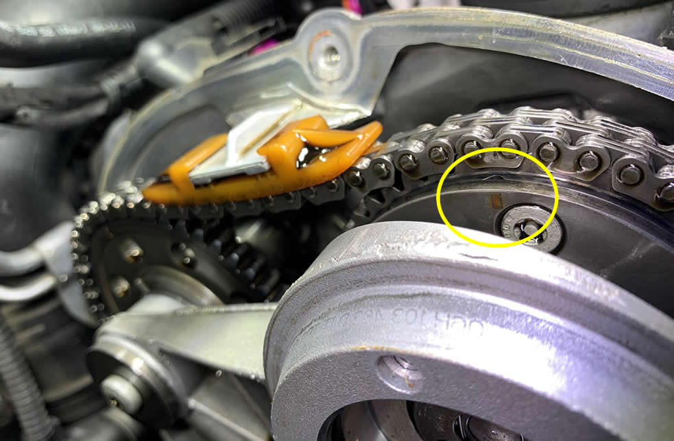
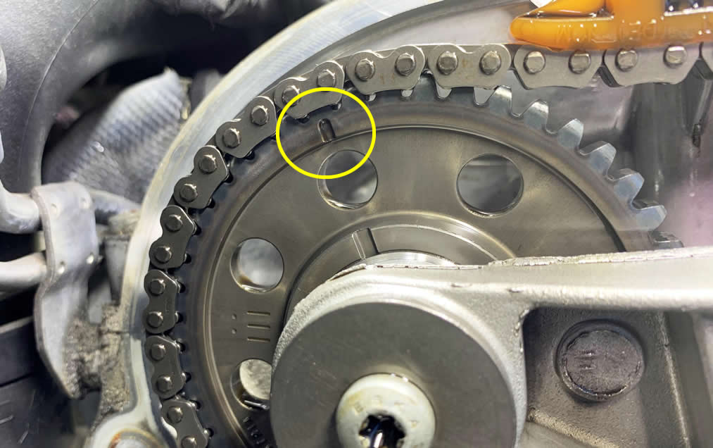
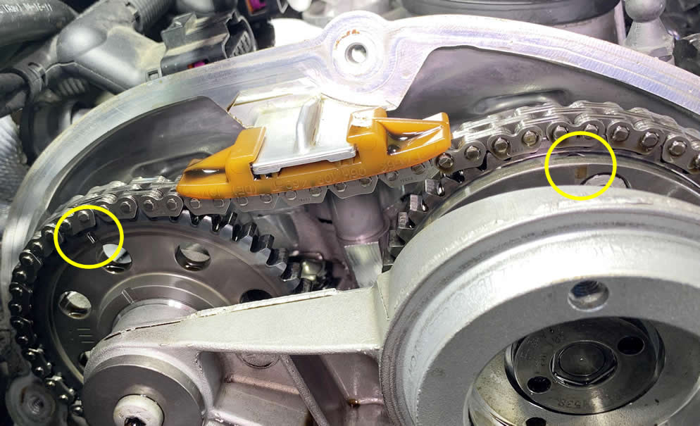
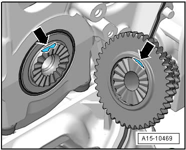
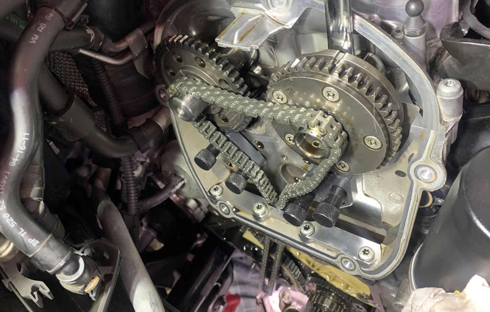
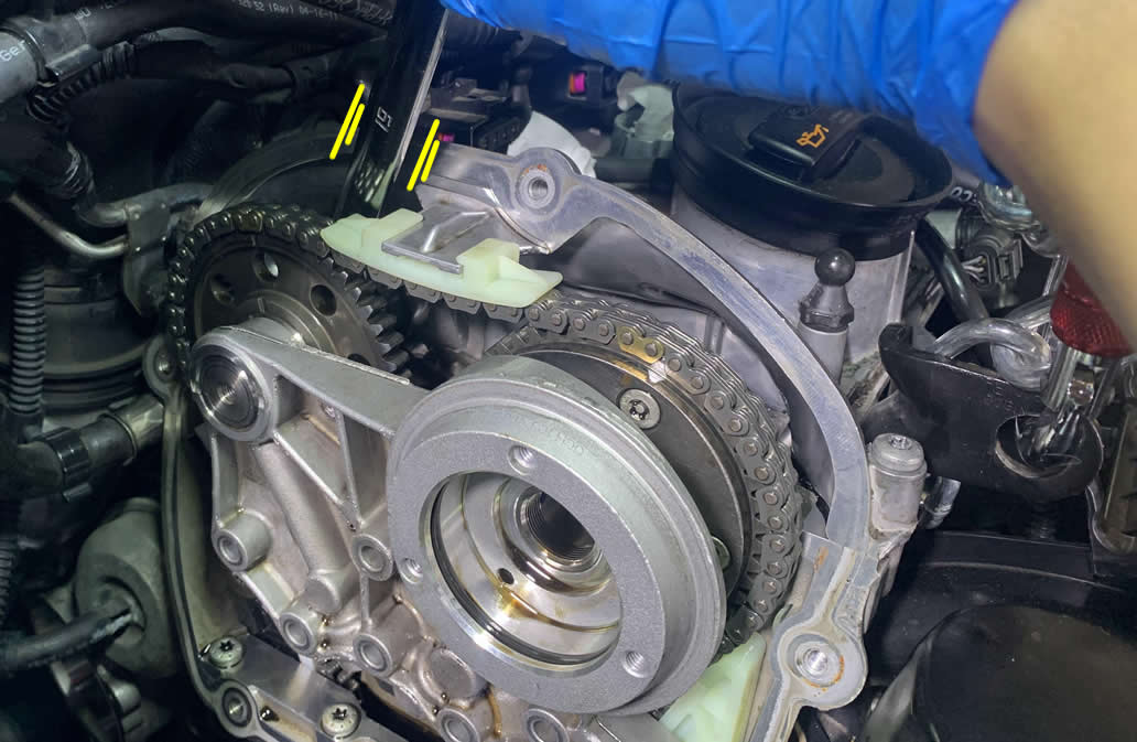
Now that you have the cover out, you should see the Exhaust Camshaft sprocket (left side) and Intake Camshaft Adjuster sprocket (right side) as well as the main timing chain that connects them. Pay attention to the marking on both of these sprockets, but don’t touch anything just yet.
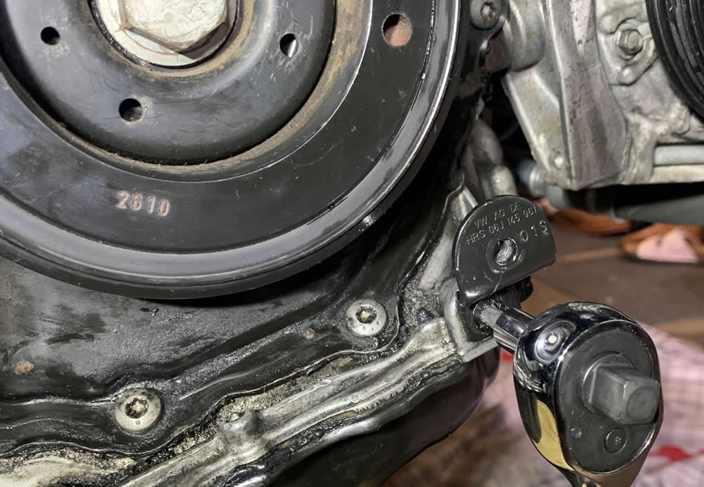
We need to get the crankshaft to a position known as Top Dead Center before we perform any sort of works on the timing chain system. This is rather the most crucial yet simple step in this entire repair job. If you fail to do this, your timing will be messed up and the engine could literally eat itself.
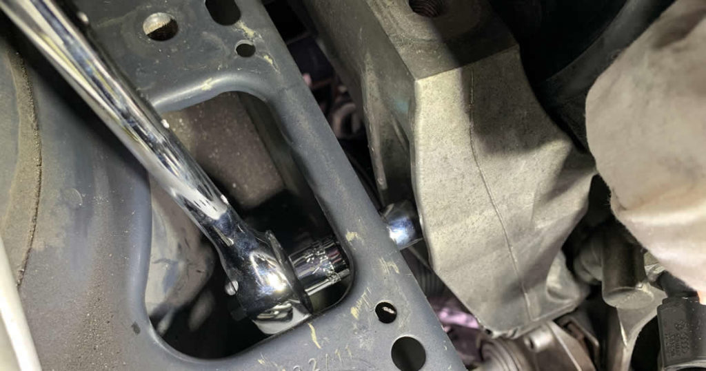
First, grab your ratchet + a 15/16 socket and get under the car. There are two small triangle notches on the crank pulley if you pay close attention. You need to turn this roller clockwise to eventually line it up with another triangle marking right on the lower timing cover at the 4 o’clock position. Some models also have another indicator at the 12 o’clock position.
The upper timing chain sprockets should start to look something like this as you get the crankshaft to the TDC position.
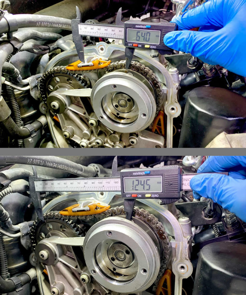
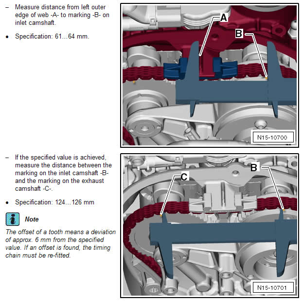
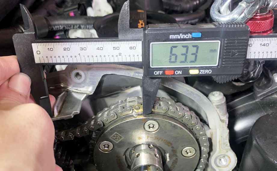
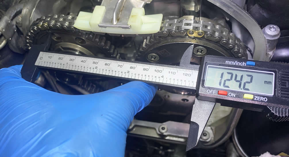
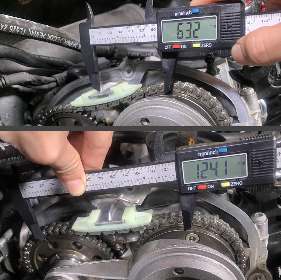
If you get to measure the distance correlation between sprockets with a digital caliper, you will find a range from 61 to 64mm between the Intake Camshaft Sprocket’s marking and the left side of the center chain guide mount. The second measurement is from one sprocket’s marking to the other (Intake Camshaft Sprocket to Exhaust Camshaft Sprocket), which should return between 124mm to 126mm.
- Intake Camshaft Sprocket Marking to Center of Chain Guide Mount: 61mm-64mm
- Exhaust Camshaft Sprocket Marking to Intake Camshaft Sprocket Marking: 124mm-126mm
1 – Remove the Crankshaft Roller and the Lower Timing Chain Cover
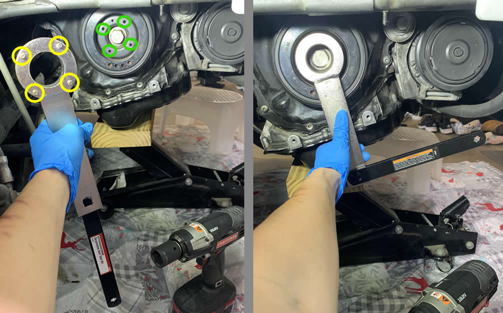
We’re ready to uncover the rest of the timing chain assembly. Grab your Torque wrench or a breaker bar + 15/16 socket and the special counter-hold tool (T10355) from the Timing Chain toolkit, we are going under.
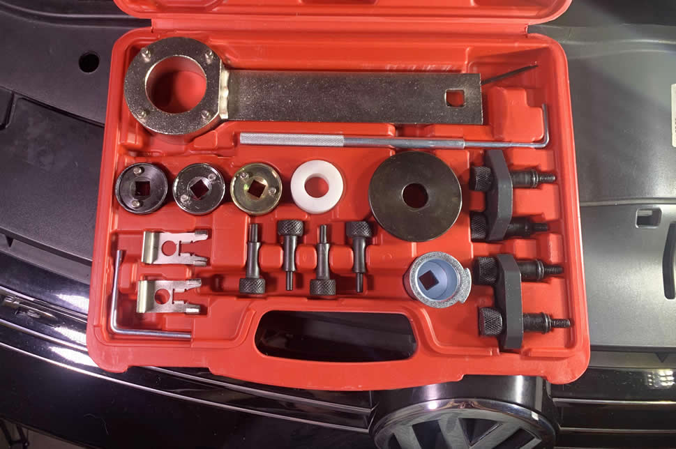
The special tool has 4 notches that line up with the holes on the Harmonic Damper (aka Crankshaft Pulley/Roller 551231).
Apply steady pressure on the counter-hold tool and do not let the Crankshaft roller rotates at will. The better you keep it frozen, the more accurate you can install your timing chains later. Now simultaneously turn the crankshaft bolt counter clock-wise. This bolt is torqued to over 110 ft-lbs so you bet it will put up quite a fight. It’s very easy with a Torque wrench however.
As you remove the roller, immediately put the spacer from the Timing chain toolkit onto the crankshaft bolt, and put the bolt back on. We don’t want everything fall apart when we take off the cover.
![]()
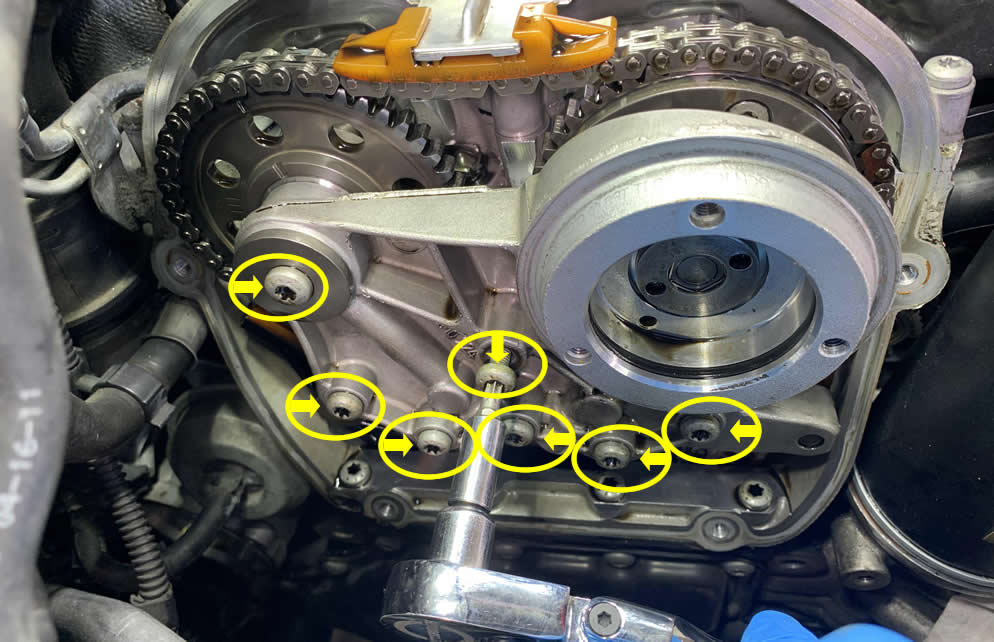
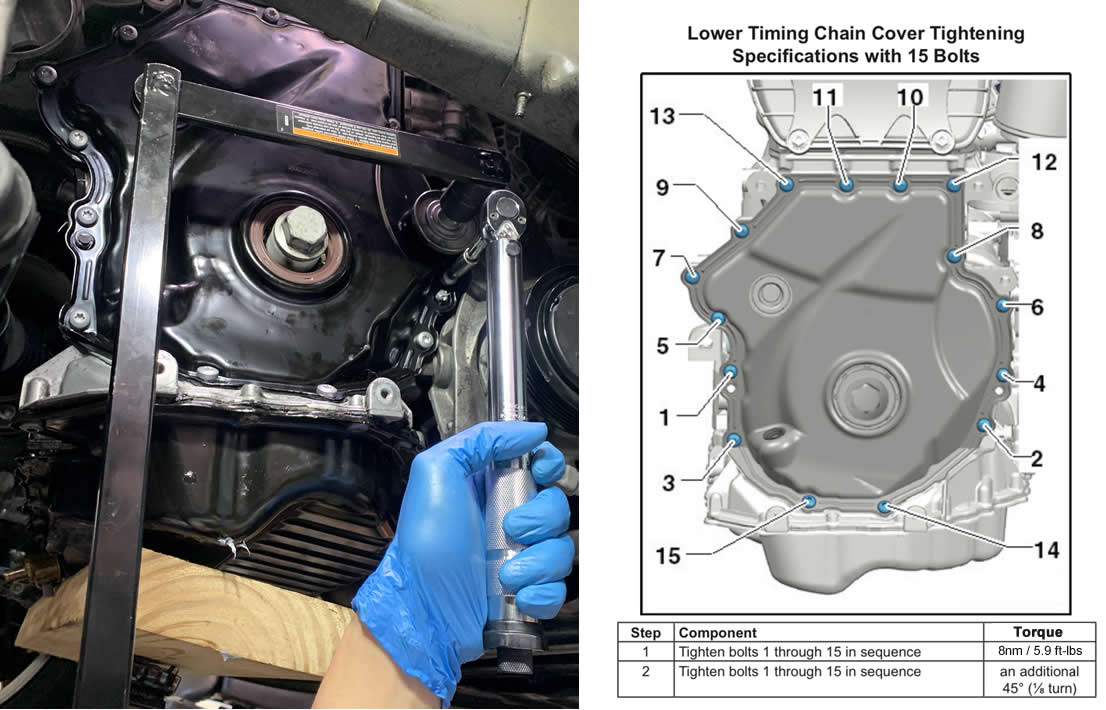
While you are still under, we are going to remove all 15x T30 bolts that secure the lower timing chain cover.
There is this one bolt that hides behind the serpentine belt tensioner. Fortunately we removed the serpentine belt tensioner roller earlier, which gives you more room to access this bolt now. After some advanced geometric computations, I decided to use my knee as leverage to push the belt tensioner out of the way.
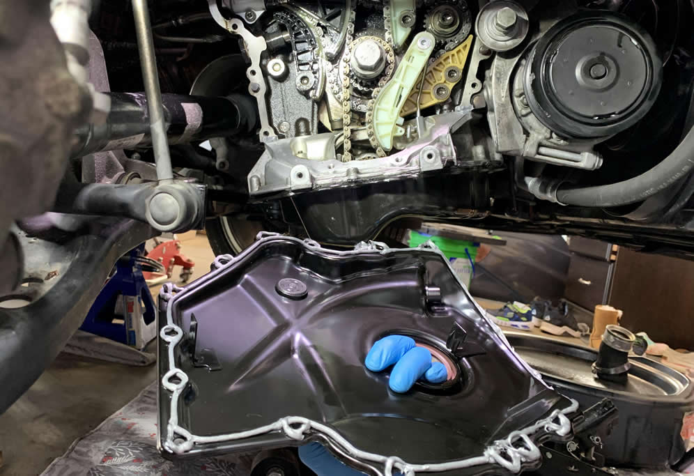
Even though with the bolts off, the cover is still attached pretty tightly to the engine block thanks to the sealant. Grab a flat-head screwdriver and prying it off gently from the top and then make your way down.
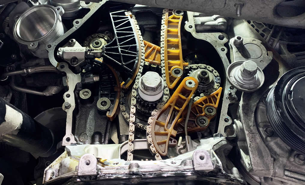
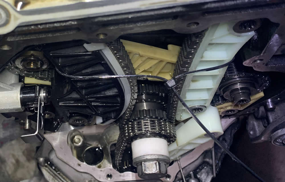
Here you can see where the Timing Chain chamber sends their regards.
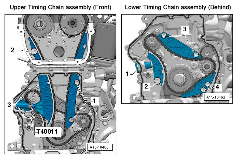
All numbers in the diagram below will help you visualize most of the bolts that we will be removing from the Upper and Lower Timing chain assembly.
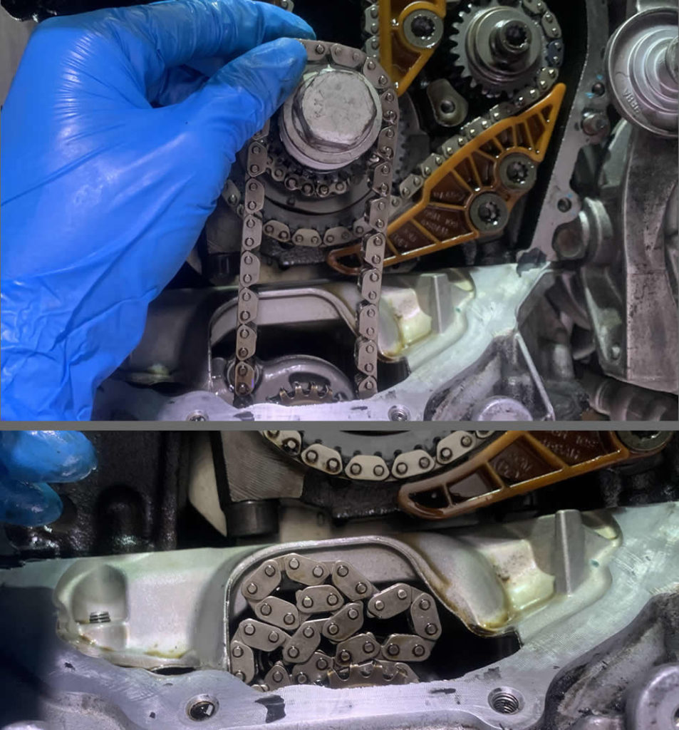
Now you should be familiar with the two slender guides on both sides that direct a long metal chain from the lower crankshaft to the upper Intake and Exhaust gears. Use a pair of zip ties and do your best to keep the tension as perfectly intact as possible on these chain guides.
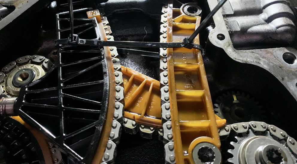
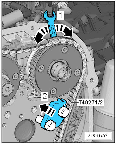
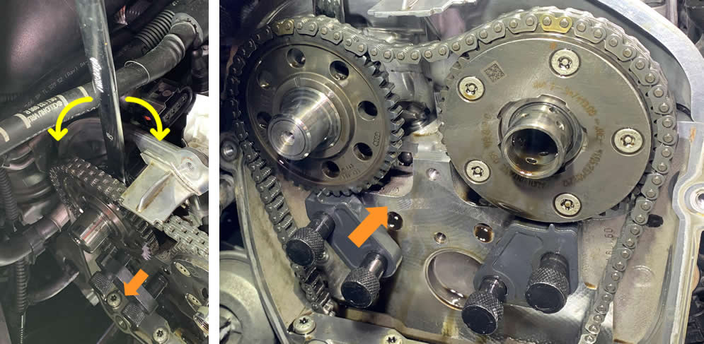
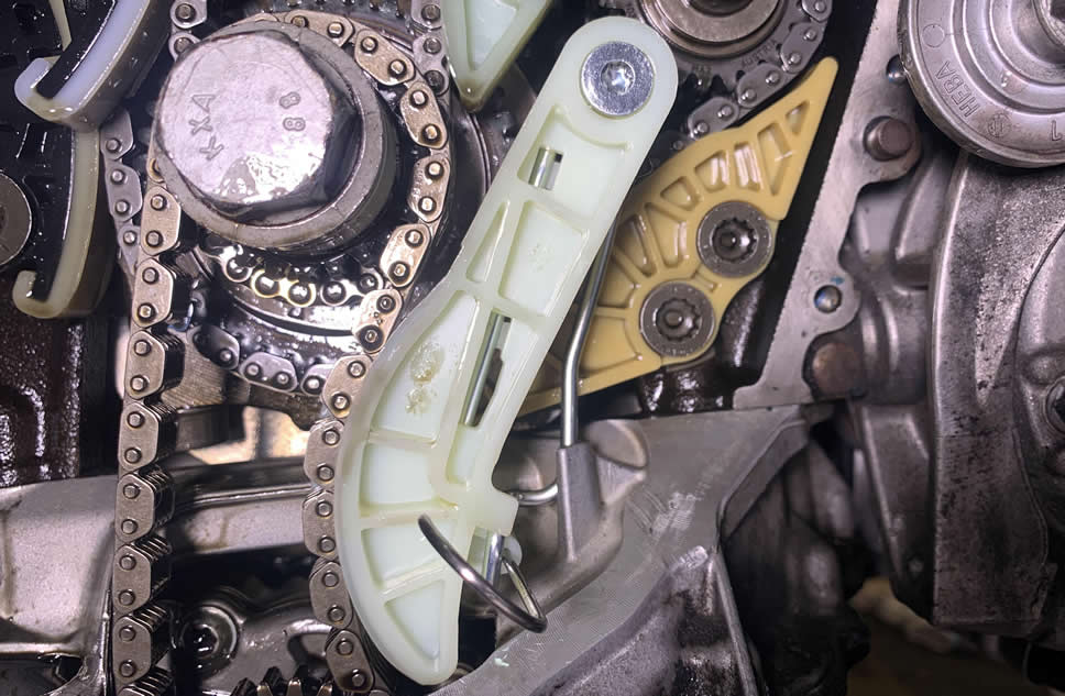
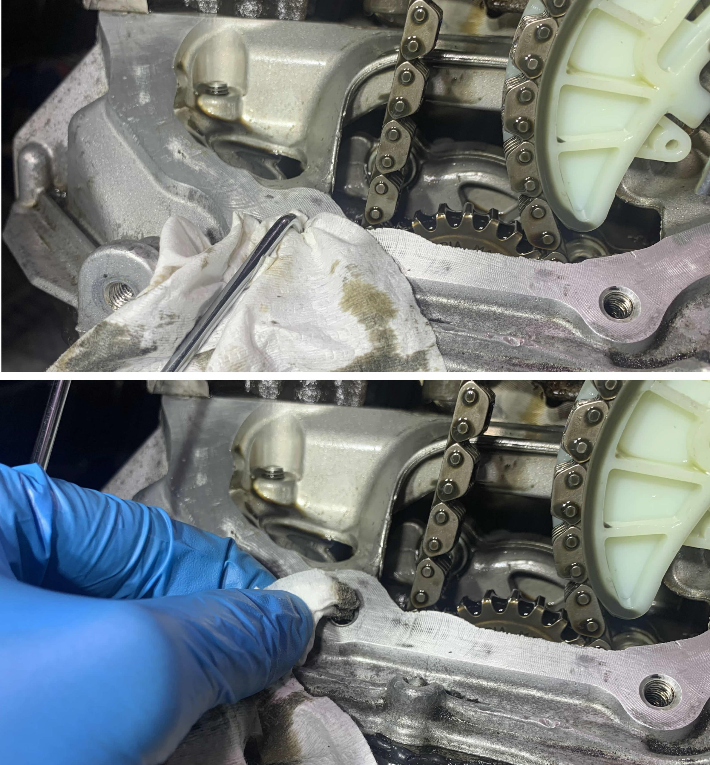
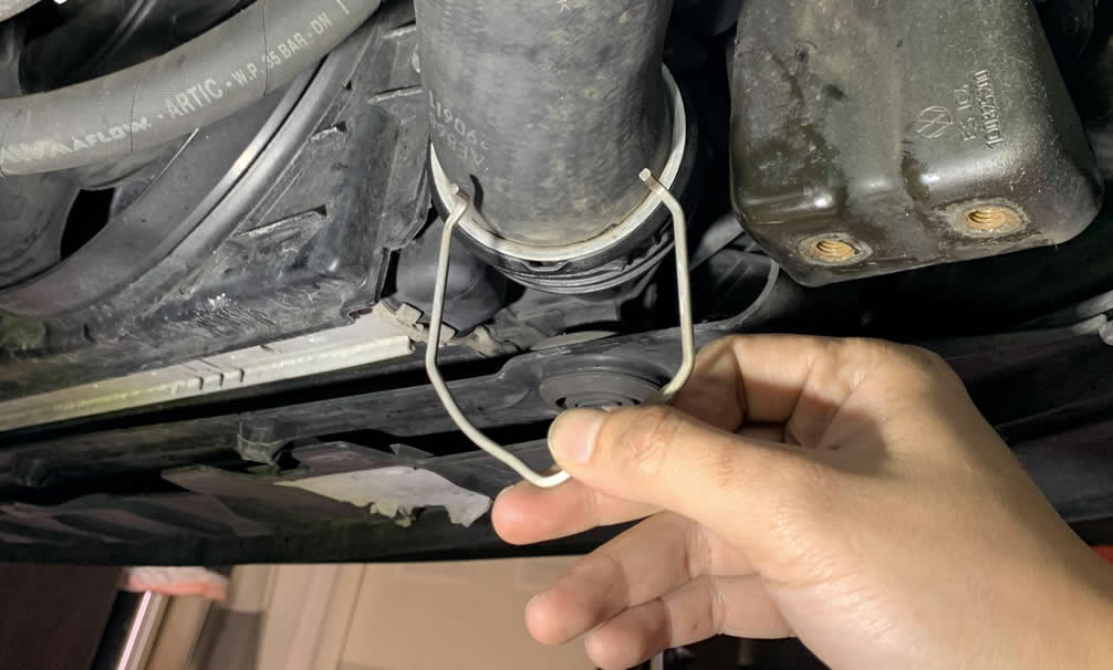
Let’s compress and lock the oil pump chain tensioner.
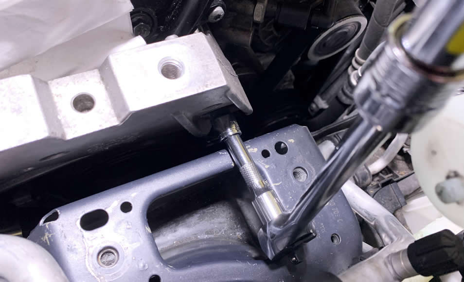
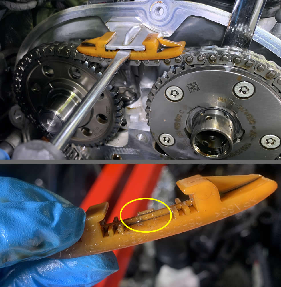
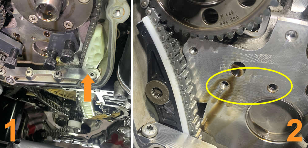
Compress the left side of the rail guide as far right as you possibly can, until the little hole on the guide itself (1) passes over the metal clip (2). This allows you to slide a pin from the Timing chain toolkit into that hole thus locking the tension that applies to the oil pump chain.
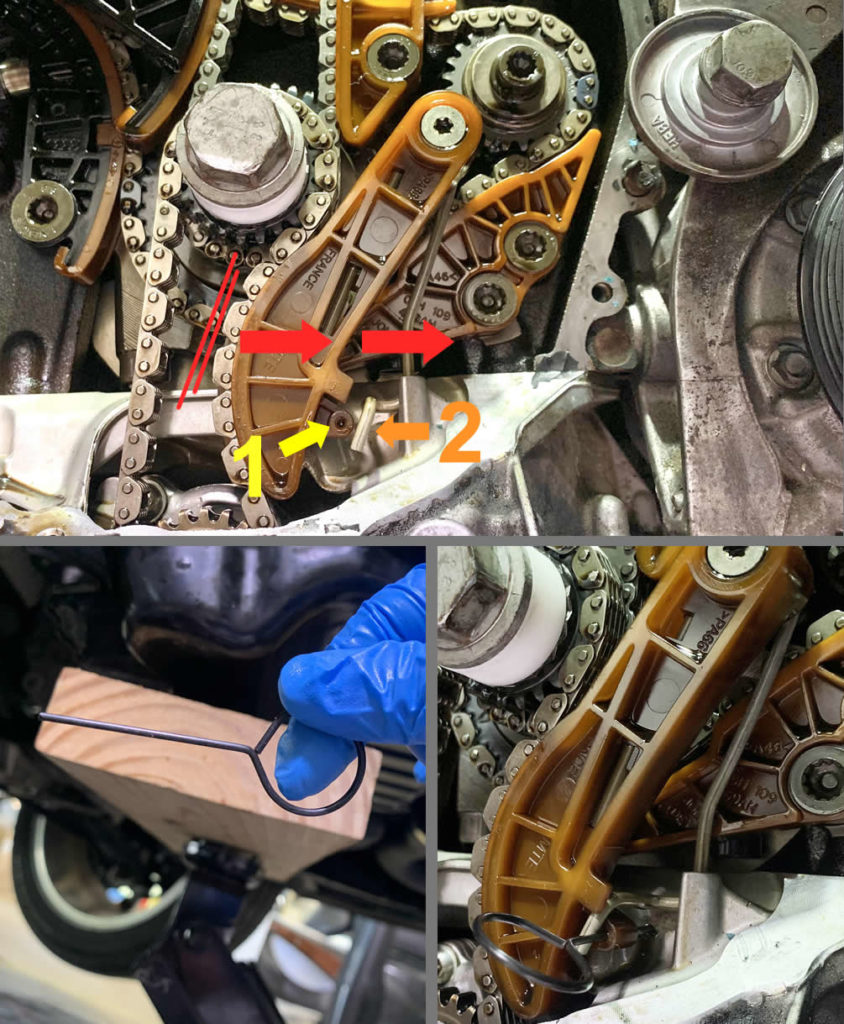
Now it’s safe and easy to get the Oil Pump guide tensioner out with a T30 Torx bit.
Lift the chain off the crankshaft sprocket and settle it kindly in the oil pan cave right below. It is not necessary to replace this chain.
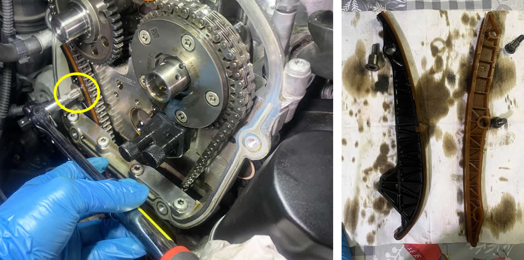
Now let’s remove seven T30 Torx bolts from the cambridge (06H103144K) above by the upper timing chain gears.
When you take a peek behind the cambridge, you will see the camshafts themselves. There is a notch on each of the two camshafts where you can stick a 18mm/19mm wrench in, to either counter-hold or make small adjustment on the sprocket’s timing.
Within the large opening of the cambridge, you should see the Camshaft Timing Solenoid (aka N205 valve, 06H109257A). You need to remove this valve before you can take the cambridge off. And in order to do that, you will need the special assembly socket (T10352) from the Timing chain toolkit.
Use a 18mm wrench to prevent the camshaft from turning and blow up your timing precision, turn the ratchet equipped with the special socket CLOCK-WISE to break the valve loose.
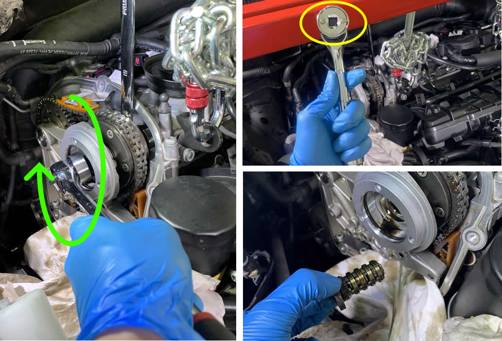
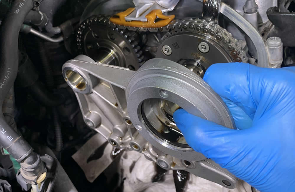
Carefully slide the cambridge of the camshafts. Both sides must come out evenly to avoid damage to the shafts.
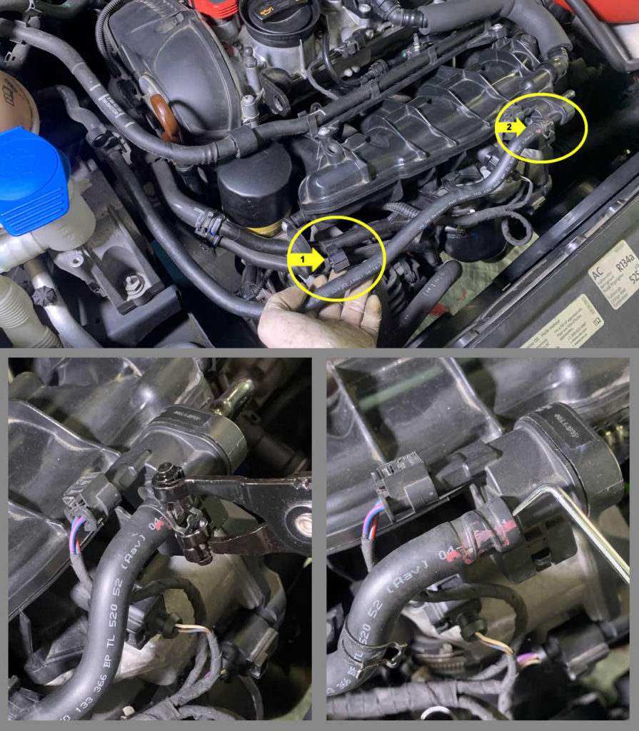
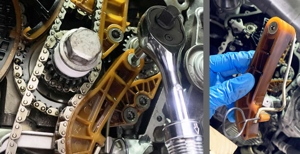
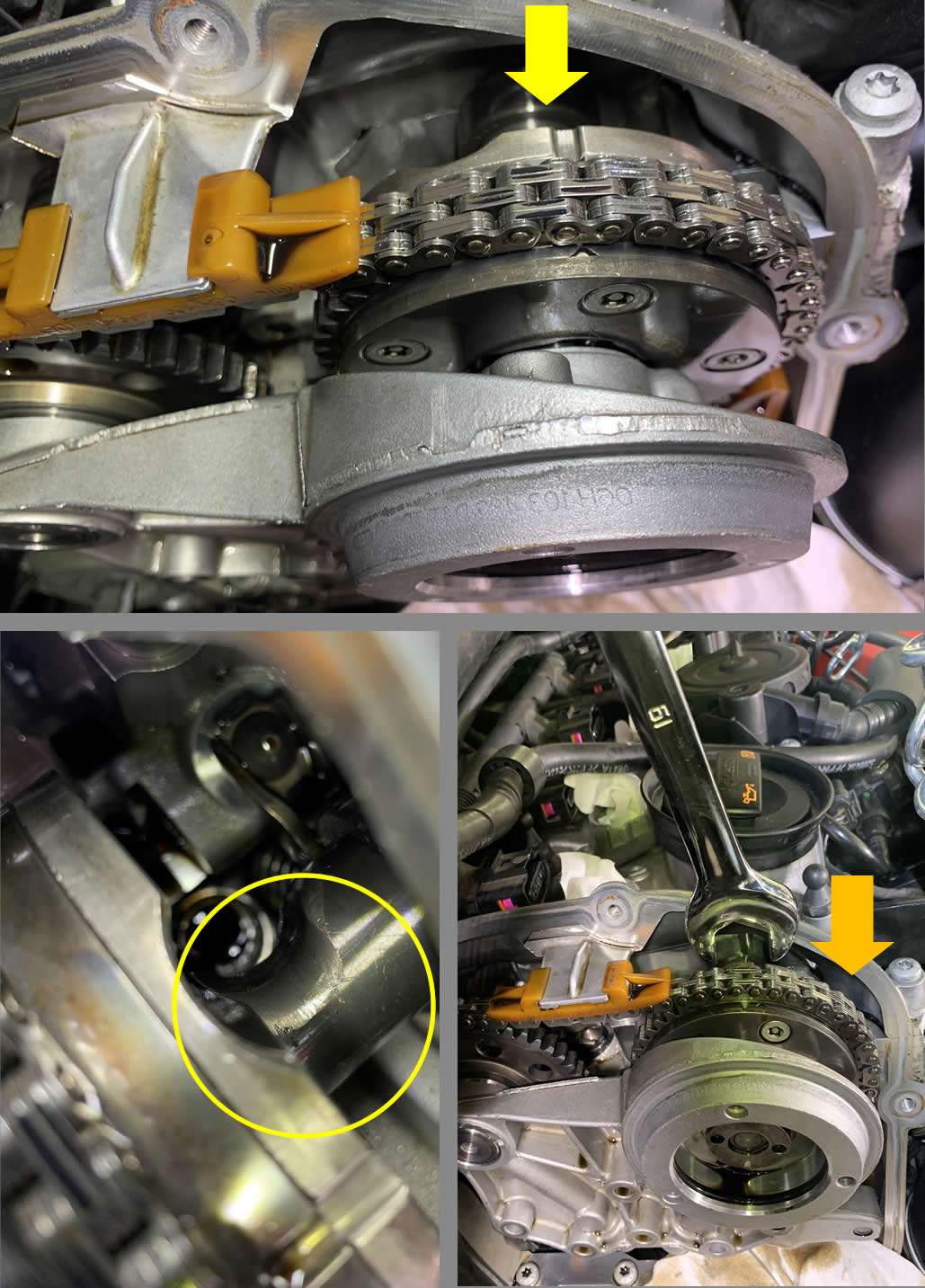
When people say they have an old timing chain tensioner and need replacement, they often refer to the Upper Timing chain tensioner.
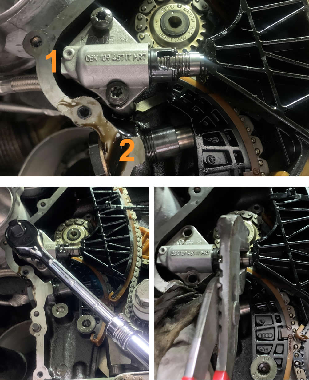
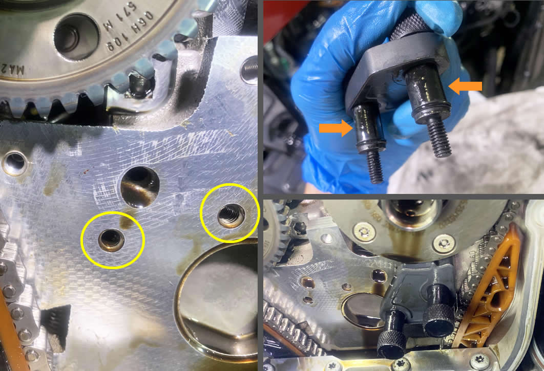
There are two tensioners sitting next to each other, the Upper timing chain tensioner (1) is right above the Lower timing chain tensioner (2). Use a T30 Torx to remove the two bolts that attach the Upper timing chain tensioner (1) to the block. Skip the Lower timing chain tensioner (2) for now.
Then you can use a pair of pliers to gently pry it off.
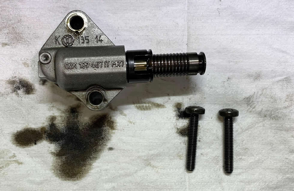
The Upper Timing chain tensioner (06K109467K) and two N10554005 Torx bolts.
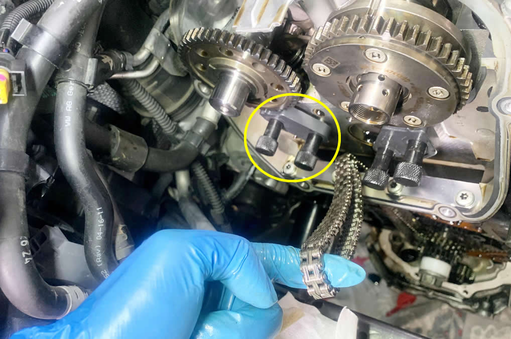
With the Upper timing chain tensioner off, you should be able to remove the cambridge much easier if you could not do so earlier. Behind the cambridge are the holes for the 6 of the 7 bolts that attach the cambridge to the block earlier. We will utilize these holes for installing the gear lock pin (T40267) from the Timing chain toolkit.
Spread some oil on the bare part of the lock pin’s bolts and then secure the device to the block using the existing hole pattern. You can slide the lock in and out to stop the gears from rotating. If the teeth don’t line up, use the 19mm wrench to slightly adjust the shaft.
When the Intake Camshaft sprocket is locked, then it’s time to cut ties.
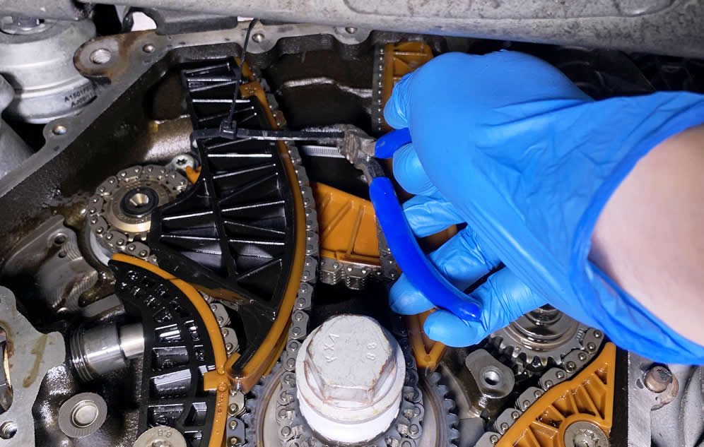
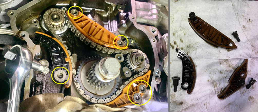
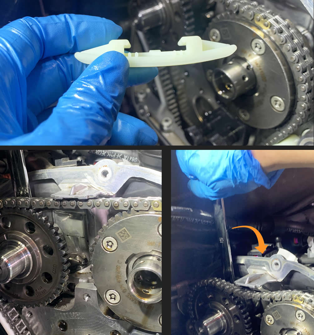
Now from the bottom, use a T30 Torx to remove the right chain guide that’s secured by 2 bolts. Then you can slide the guide down to remove it.
There is only 1 bolt that holds the left chain guide.
The last chain guide is the top-mounted. You can stick a flat screwdriver in and pry it off. It’s a lot harder than it looks, especially when everything is greasy and slippery.
Install the second lock pin for the Exhaust Camshaft sprocket, then remove the entire Upper timing chain by dropping it down from the top.
If you planned on replacing the Lower timing chain components, you absolutely did not know what you signed up for. So let’s get right to it.
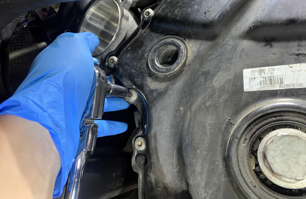
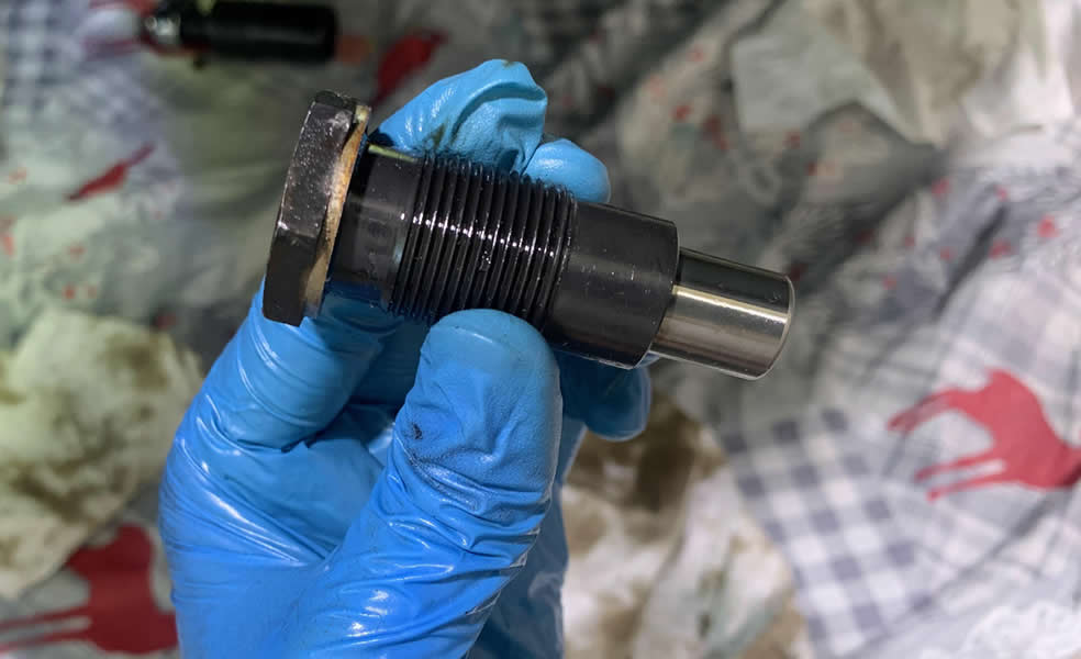
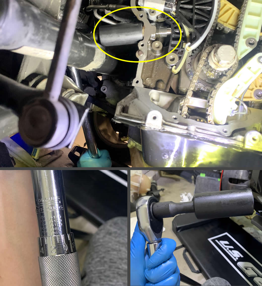
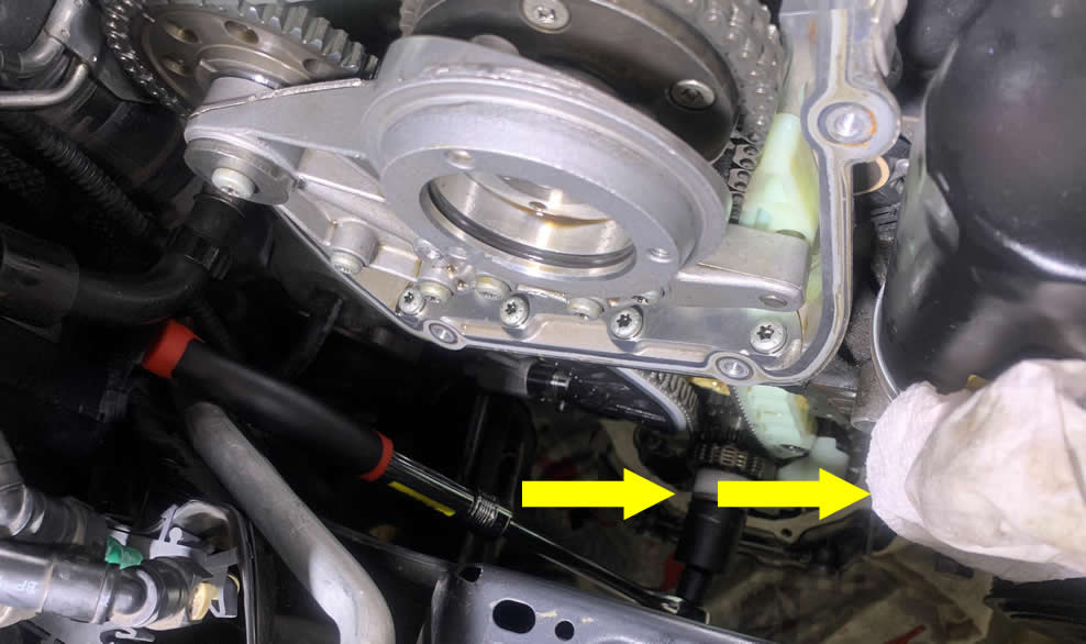
You need a 27mm deep socket and an extendable/long ratchet to reach the Lower timing chain tensioner. You should be able to remove it this way:
The Lower Timing chain tensioner.
There are 1x medium-length chain, 3x chains guides and a total of 5x bolts for the rest of the Lower timing chain assembly.
If your Timing chain replacement kit has a new Crankshaft sprocket, you can follow the next section to replace it after you have these guides removed.
I’m replacing this Crankshaft sprocket so I took it off for the new one. Remember to put the crankshaft bolt back on once the replacement is in place.
Here’s a quick illustration straight from ElsaWin.
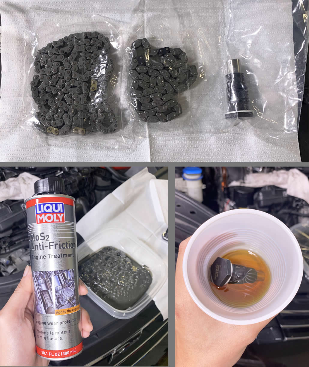
Many indie shops I know put the new chains on directly as they often rush through the job, but I prefer to take it slow and give these chains a coat to protect them on the first dry start.
I soak the new chains in Liqui Moly MOS2 Anti-friction Engine Treatment; and the Lower Timing chain tensioner which is driven by hydraulic, in engine oil.
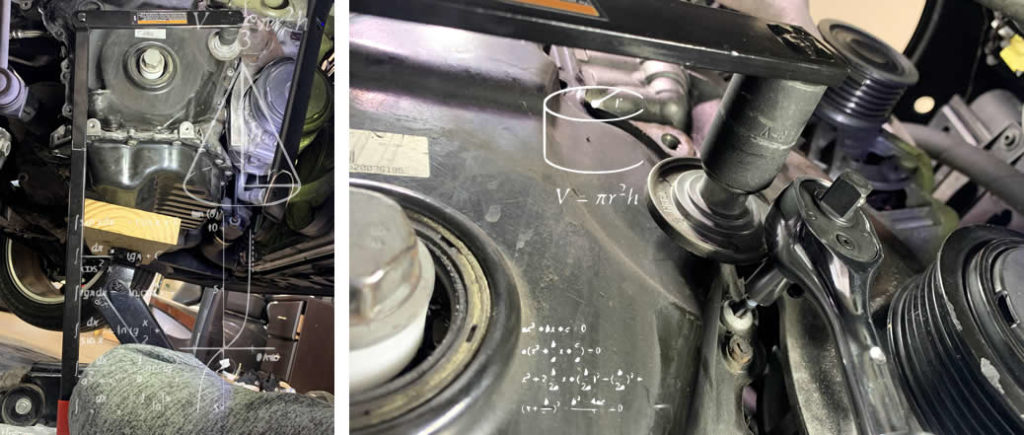
It is a narrow space to get your eyes on these gear and sprocket, but do your best to get to them. These components reside on the right handside of the lower timing chain compartment.
Use your finger to rotate the intake-side balance shaft gear until its yellow mark sits between the two dots of the sprocket below it. It may take up to 7-8 rotations to get these indicators lined up properly.
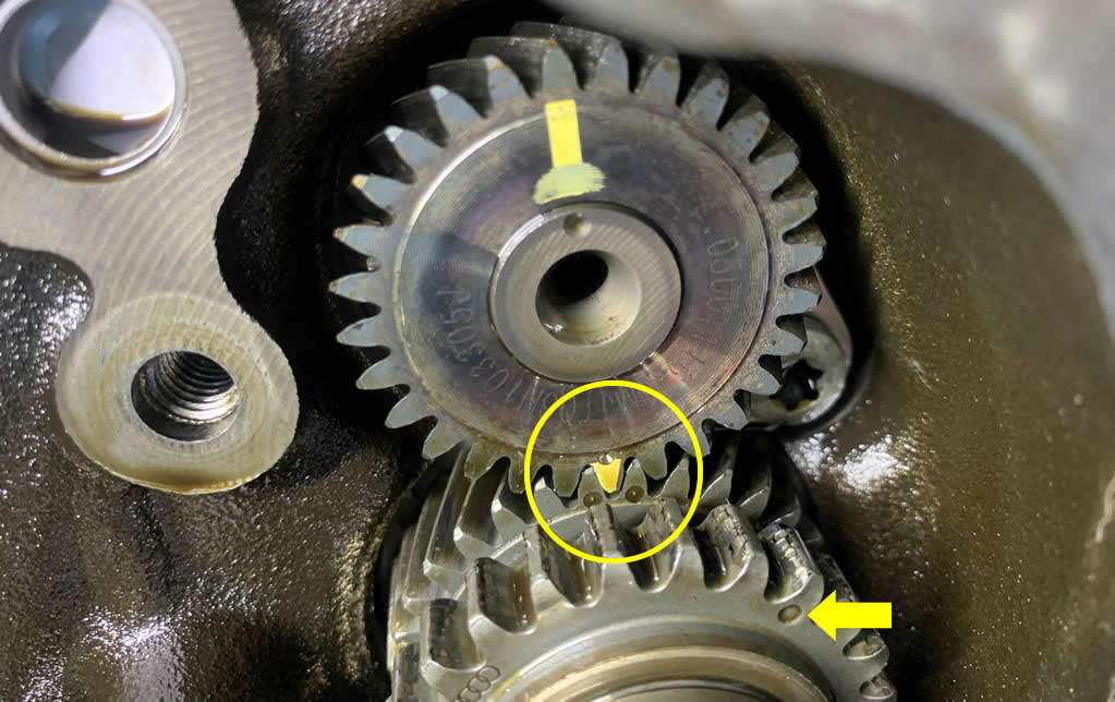
The yellow arrow above indicates where the first dark color-coded link on the Lower timing chain (medium-length) will go on. There might be a shorter chain in your replacement kit that is for the oil pump, but we don’t need to change that one.
Now this is what you have been waiting for: it is time to put the chain on!
Each dark-colored link on the chain must line up accorndingly with a marking on the sprocket. The markings are either indented circle or triangle pointing at the tooth that meets the link on the chain.
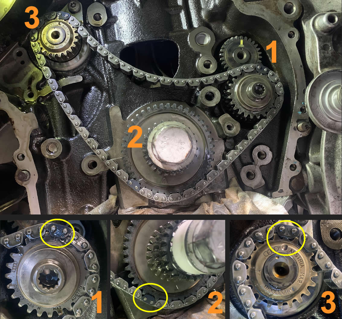
Once you have everything looking all nice like the photo above, we can go ahead and install the chain guides for the Lower Timing chain. I like to give each one of them a light coat of oil prior to the installation. How do you like my fried chick wings and bites?
There are three guides for you to put them up. Yet there is only one way for them to go on so you can’t go wrong with this.
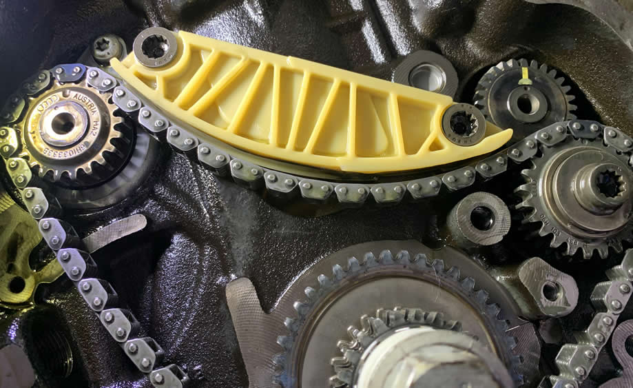
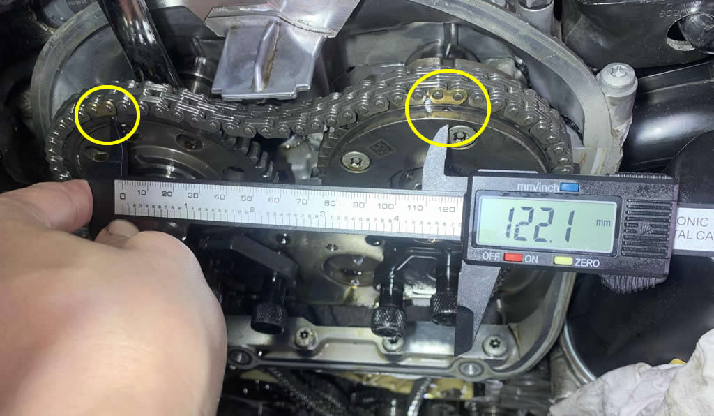
Dangle your longest chain like this. Mine looks darker because it has been soaked in lubricant all day. Some day somewhere, that was what she said.
The color-coded links on the chain line up perfectly with both the Intake Camshaft sprocket marking and Crankshaft sprocket marking.

Uh oh.
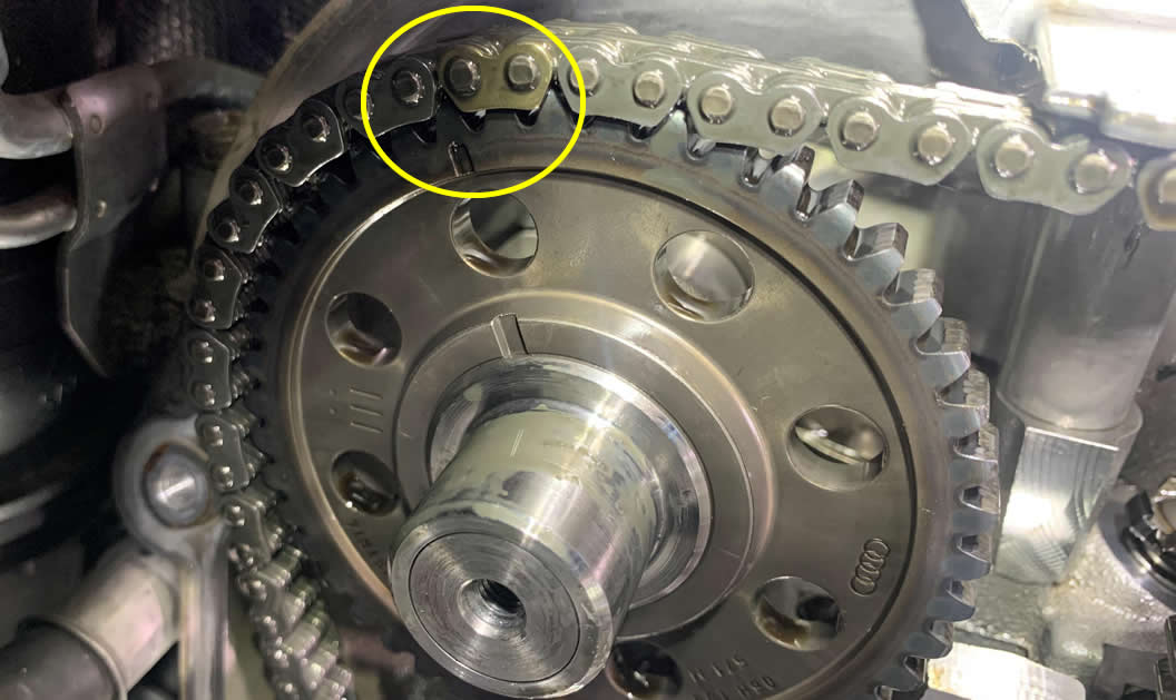
The link missed the marking on the Exhaust Camshaft by a tooth! That’s it boys, it’s over. Pack it up and call the towing service we’re taking this nightmare to the stealership :(
So first thing first, take out your digital caliper. We’re going to measure the correlation between the Intake Camshaft marking and the center top mount.
If your value is between the acceptable range of 61mm to 64mm, then you know we ought to adjust the Exhaust Camshaft gear instead –or vice versa.
Use your 18mm/19mm wrench and grab on to the back of the shaft you want to make adjustments. Slide the lock pin out of the engagement point, then apply small rotation left or right to the shaft until you’re satisfied.
Then slide the lock pin back in, strap the chain on and make sure the markings line up.
This is the approximate reading for the correlation between the Intake and Exhaust Camshafts’ markings, locked but under no tension.
Now you can resintall the new chain guides in place. Start with the right side first, slide it up from the bottom.
In order to be able to get the left side chain guide in place, you will have to remove the lock pin.
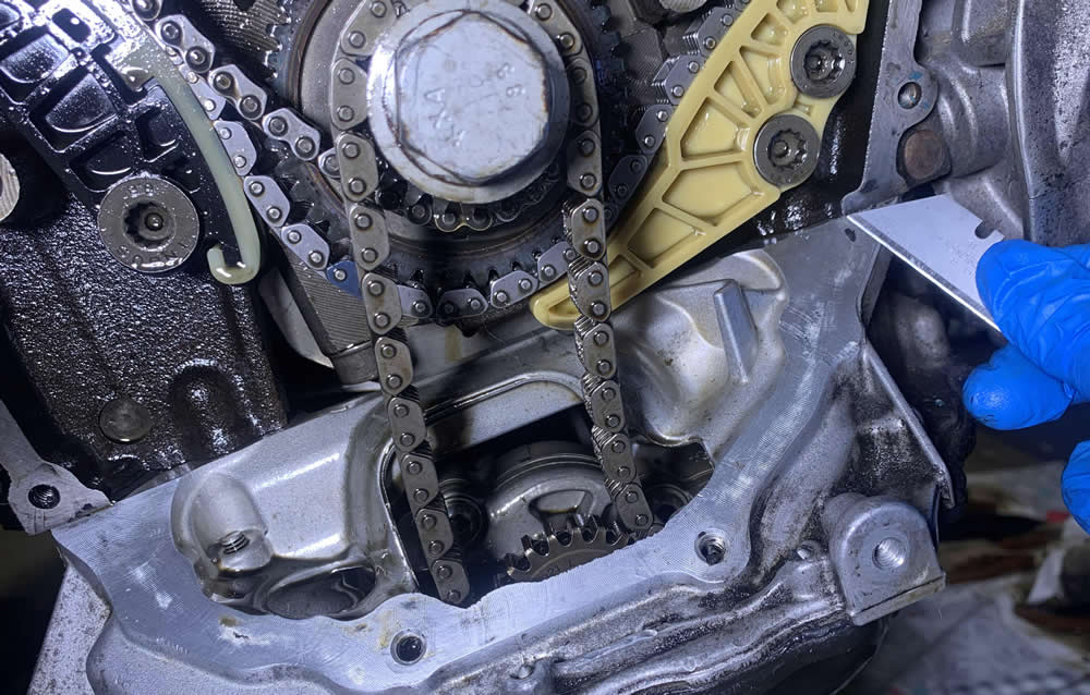
It might also be a good time to clean up the surface of the Lower Timing chain area where the cover goes on. You can do that with a razor, but be gentle.
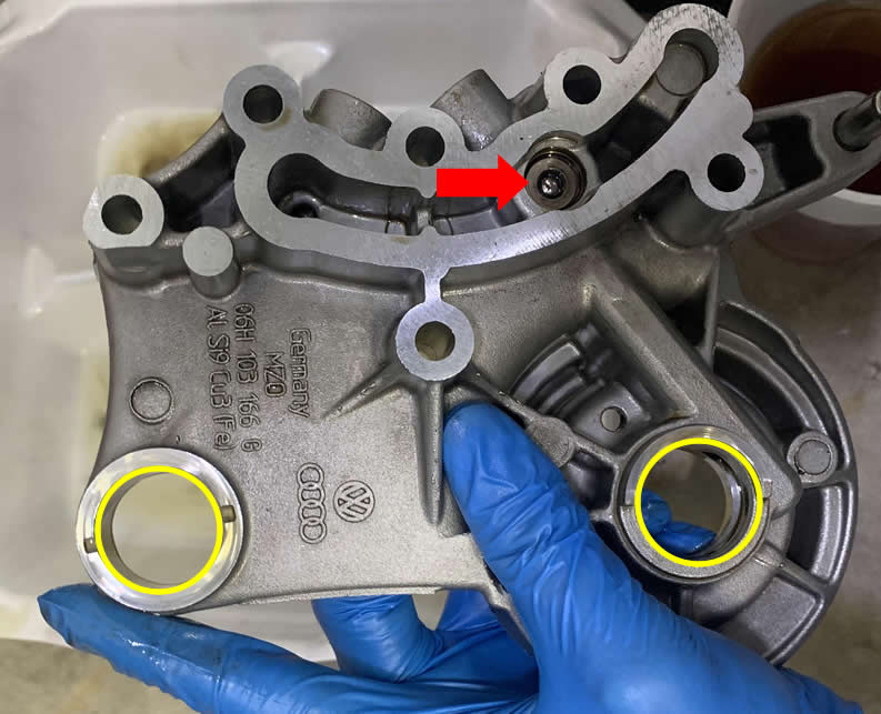
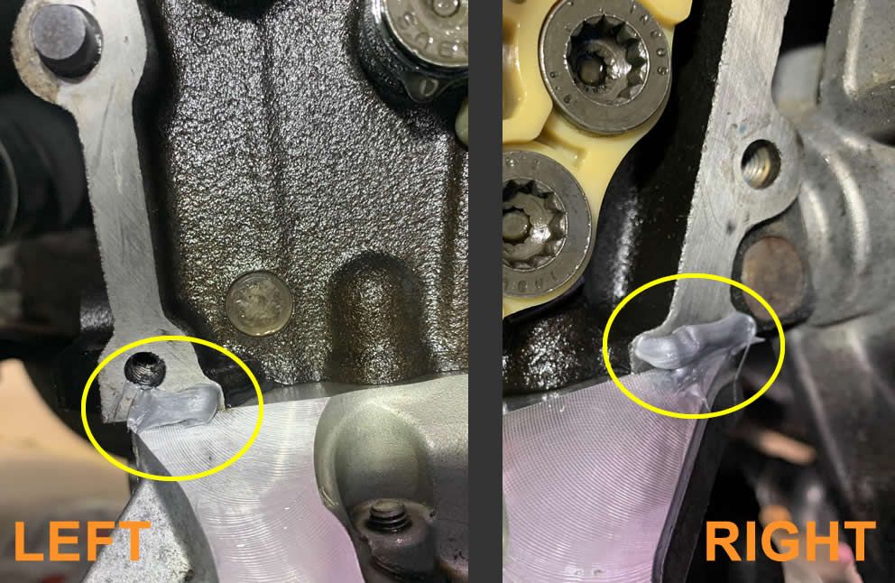
We just need to do a quick prep on the Lower Timing chain tensioner, by applying a thin layer of the same gasket maker you are going to use on the cover, onto the tensioner’s metal o-ring. Some models have a separable o-ring like this, some don’t.
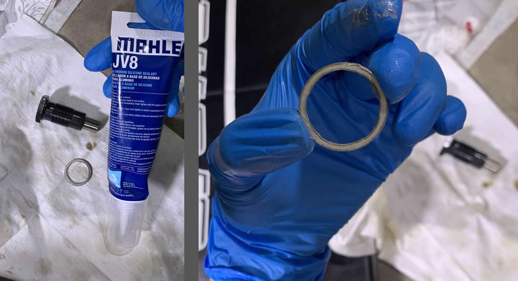
Hand-tighten the tensioner into its location.
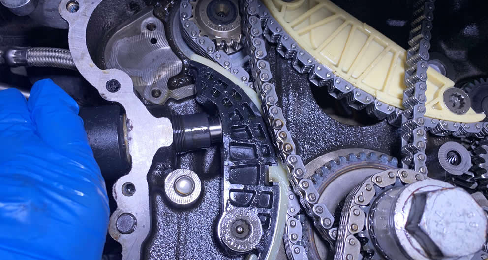
Next, reinstall the new Upper Timing chain tensioner in place.
You want to simulate a portion of the tension generated by the tensioner without actually pulling the locking bracket, because we still have some works to do. So go ahead and squeeze both side guides of the Upper Timing chain together to the center and ziptie them in this position.
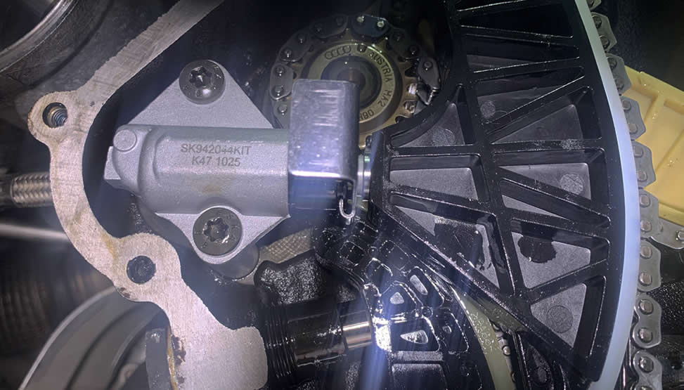
While you are still down here, let’s take care of the last tensioner –the one for the oil pump chain. Nothing too crazy about putting this guide back in place. Pull the pin to release the tension when you are done.
With both the side guides installed, the Upper Timing chain should already tightened up. If you have a hard time trying to get the top guide reinstalled, use your wrench and slightly rotate the Exhaust Camshaft clock-wise. You should feel the resistance, don’t overextend the turn.
Here we are at the semi-final Camshafts’ markings correlation measurement reading.
Before you put the cambridge back on, give it a thorough inspection. Some people find crack that shouldn’t be there. Also give the inner circular areas (yellow) where both Camshafts go in a thick coat of oil. This will help you put the Cambridge on much easier.
When you reinstall the Cambridge, it is extremely important to slide both sides in evenly. Do not push one side in first and then the other, doing so will damage the camshafts. If at some point you feel like it’s stuck, turn the Exhaust Camshaft slightly left and right using the 18mm/19mm wrench to aid Cambridge’s movement.
Give it a little tap with a rubber mallet at the end when you think it’s all set.
Take out your 3/8″ Torque Wrench and the 27mm Deep Impact socket, we are tightening the Lower Timing Chain Tensioner for good.
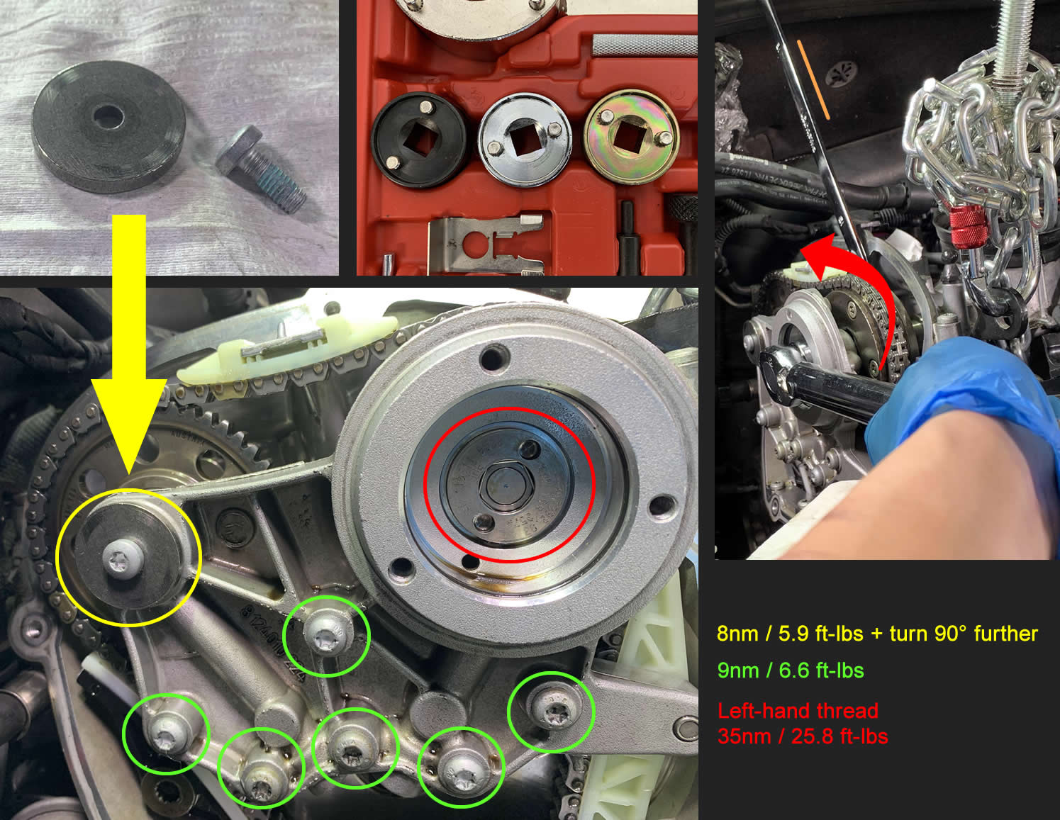
Before you pull the locking bracket from the Upper Timing chain Tensioner, it’s worth it to go over and double check the torque on every bolts securing the chain guides once again.
Now we secure the cambridge and camshafts assembly together. A few notes that you may them helpful:
- The little M6 bolt (yellow, N10029205) that goes on the Exhaust side of the Cambridge must be replaced, you cannot reuse the old one. These bolts are also used for the Lower Timing chain cover and they all have an oil-resistance coat that prevent them from backing out when the engine oil penetrate the thread.
- You can reuse the other 6 bolts (green, N10470703) to secure the Cambridge. I recommend a replacement if their heads are too worn out.
-
You need the special donut socket tool to reinstall the N205 Valve (red, 06H109257A). It is left-hand thread therefore you need your wrench to counter-hold the Intake Camshaft while you make the counter-clockwise turn of 25.8 ft-lbs.
Get the final readings for your Intake and Exhaust Camshafts with the digital caliper.
If you rotations are successful, it’s time to practice dry-fitting your Lower timing chain cover on-off a few times. This way you know the precision required to not mess things up when there the gasket sealant is on the line (literally).
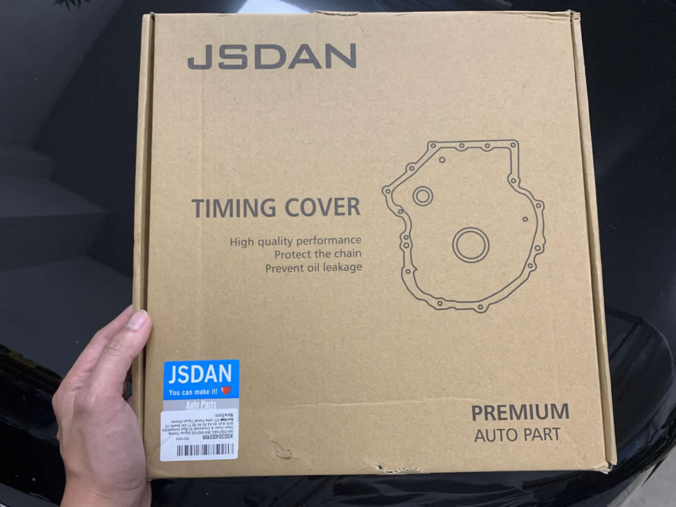
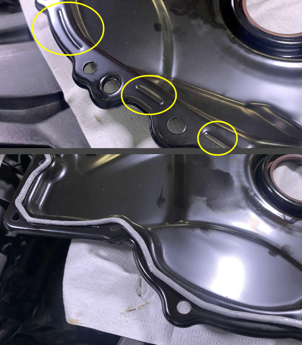
A little side note: I ordered several Lower timing chain covers from Amazon to check their quality and whether they are up to par with the OE cover. In short, only one made it while others have issues here and there. Sometimes, Amazon ship you a used one even though you ordered new –shady people swapped their old cover, kept the new one and returned their trash.
This lower timing chain cover is sold by Oxygen (JSDAN store) on Amazon. It has well-packaging, solid quality, no bent edges. However, just like most other after-market covers there is no triangle marking for the Crankshaft pulley which may make it harder to put the Crankshaft in TDC position in case you have to do another timing chain replacement in the future. If that bothers you, you can order a genuine cover via ECStuning.
To practice-install the cover, you can use both hands but they must be holding on to the front side of the cover while you quickly line up the cover’s guide holes into the two pins in the engine block.
If there is some oil accumulation in these threads, do your best to dry them out.
When it’s time to apply the gasket sealant, follow the existing tracks on the edges with a steady hand and it should come out nicely. Mine was a mess (thanks, hands!)
As far as I know, it is not neccessary to apply sealant around the bolt holes on the cover, but I thought while I was there –why not?
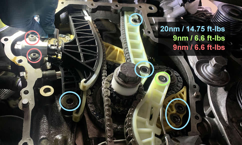
Follow this sequence and torque specs to secure your Lower Timing chain cover.
Don’t feel bad to put the serpentine belt tensioner’s pulley back on. This journey is coming to an end, Frodo.
Next we have the N75 Solenoid Valve (06F906283F) which is one hell of a challenge to put them tiny bolts back on. Good luck, it might take over half an hour just for this simple task. Hence, instead of reinstalling the stock Turbo Muffler I decided to use an after-market Turbo Muffler Delete just for the sake of easier get-around and less air flow restriction to the turbo.
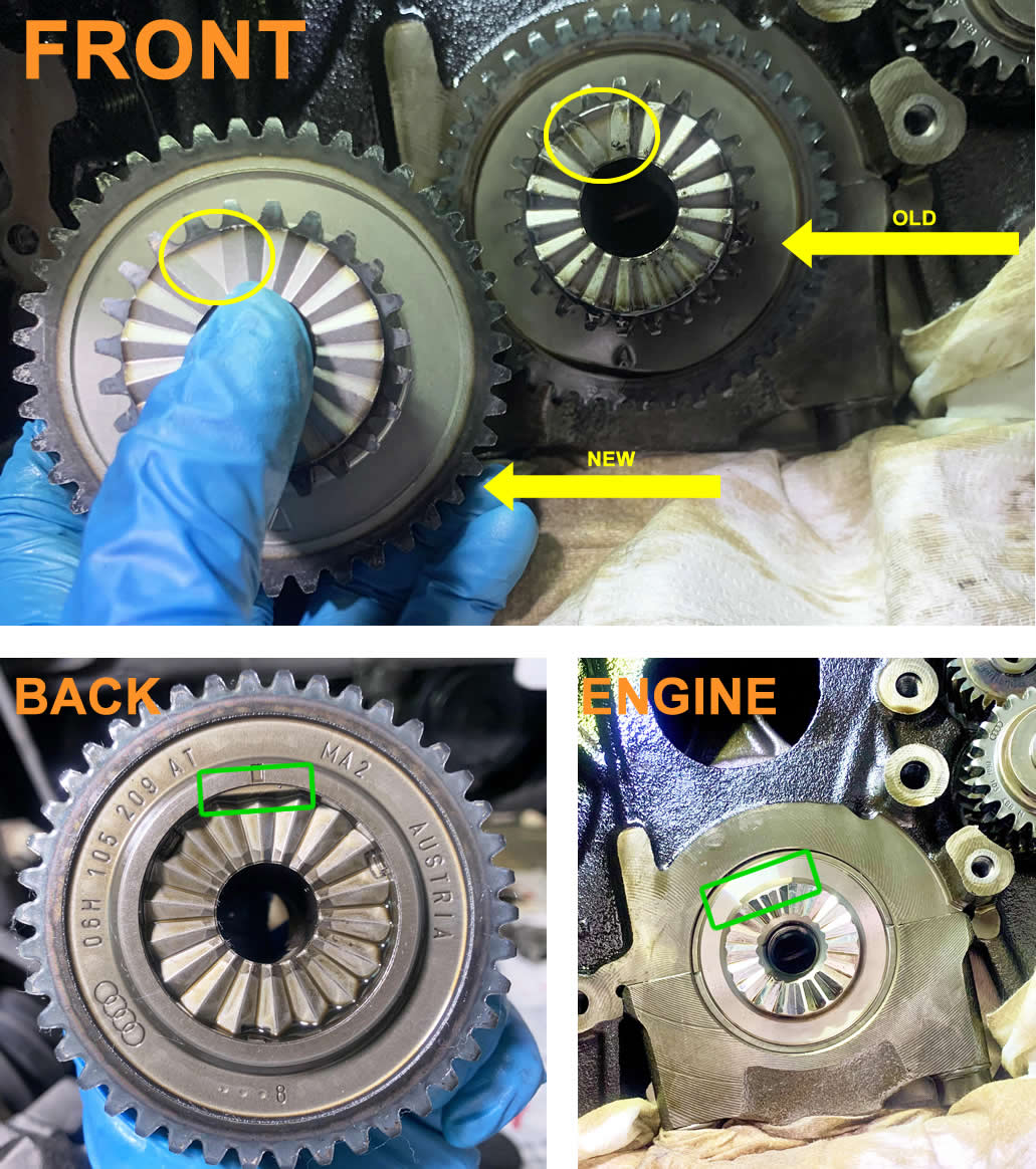
Before you put the Crankshaft Pulley (Harmonic Dampener) back onto the Crankshaft sprocket, pay close attention to the triangle keyway and make sure the pulley sit correctly.
If you worry whether the Crankshaft pulley gets on right, it helps to use a highlighter to leave a mark indicating where the triang keyway is located on the other side.
Moving on to the top. If you have new gaskets for the Upper timing chain cover, go ahead and replace the old ones now. Be sure the gasket sits tight and evenly into the housing.
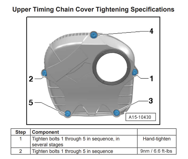
Here are the sequence steps and torque specs for the Upper Timing chain cover bolts.
While you are still here, we can put the Camshaft Adjuster Magnet (06J109259A) back on as well. Don’t forget the oil dipstick housing will also be attached to this component later.
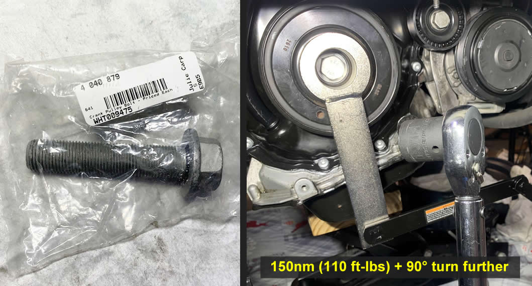
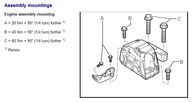
Are you ready for one of the hardest step yet? Here we are going to install the new Crankshaft Bolt into the Crankshaft Pulley. This bolt takes 150nm of torque (110 ft-lbs) and an extra 90° turn to stay snugged.
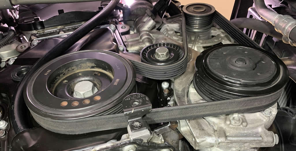
You derseve a break after that Crankshaft bolt. But if you are still on adrenaline, go ahead and put the serpentine belt on. And then the oil dipstick housing.
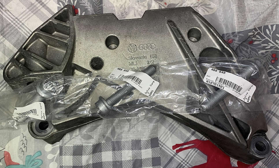
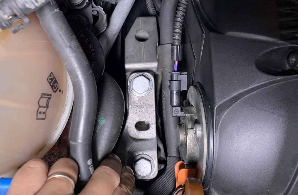
First we start with the Mount to Engine (Block Bracket) and three new M12 Bolts (N10701501). They are stretch bolts and must not be reused.
Due to the very limited space as we all know, the trick to get the bracket and bolts in place is sliding the bracket down from the top bay. Then quickly put the two bottom bolts in and raise the bracket in its proper place, hand-tighten the bottom bolts first.
Finally you can put the upper M12 bolt in from the bay above.
Now the hard part is to torque these bolts correctly.
To get to the furthest back bolt, stick your torque wrench into the abyss. Then align the M12 bit to the bolt head properly. After that you can tighten it from the top easily.
You might have to raise or lower the engine using the support bar, combine different extension to reach the other two bolts properly. Anyway, as you have gone this far I’m sure you gained enough EXP and level to tackle this like a real pro.
Here’s the challenge: drop a comment and tell us how you did it! I’ll probably enjoy reading it more than I should.
Hint in case you need for the bottom-right bolt: “It’s easier to fully torque in the near future where gravitational force shifted!”
Now we’re here at the second part of the engine mount, the body bracket (mount to body). Install the two pair of botls where one has a little stud sticking up like a morning wood.
When the car is on the jack stands, sometimes that causes the engine to gradually falls back further to the firewall.
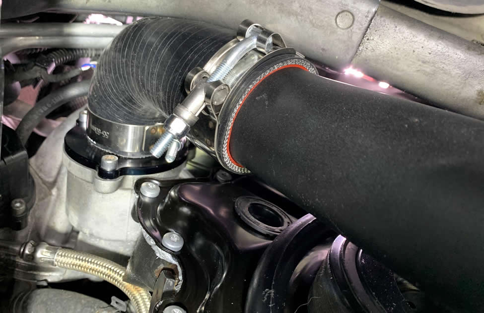
Before we let gravity influence the engine position, go ahead and put the Turbo Outlet Pipe back on. I have replaced the Turbo Muffler with the Turbo Muffler Delete and this is how it looks on mine now. Link may look at bit different at the time of your reading due to manufacturer’s revision.
Don’t forget there is the clip-on bracket for the front-end section of the Turbo Outlet hose.
I bet you remember how to put the fender liner back on and how many screws it uses. Get that done first, and put the wheel back on. Then finally you jack your car up once again but this time do it from the rear.
Don’t be afraid to that your engine might get hurt, use some force to rock the brackets into place. The holes should start to line up nicely again with the asisstance from gravity.
Install the front bolt first and tighten it to 95% of the way where you feel it snugs, but at the same time you can tell it’s still easy to rotate the bolt a little further to either direction.
Then adjust the position of the two brackets again using some squeezing and rocking movement. The second bolt should go straight in with no resistance after some wrestling between the two mounting brackets.
Double-check on the fitment of the mounts one more time, then grab your torque wrench and seal the deal.
While you are here, reconnect all the coolant hoses, breather hose and the coolant resevoir just for fun.
I’m sure it’s been a lot of fun and challenging moments (and frustrations) along the way. But you did it! You have made it halfway through!
Yes. Halfway. The real party begins the second you turn the ignition. Is it gonna work? Did you fix the problem? Do you have to take everything apart and adjust again? You never know. It could be a super smooth sailing from now, or it could be worse. I just want to prepare you mentally for what to come.
However, let’s not get ahead of ourselves. I have a few notes for you before I leave you on your own.
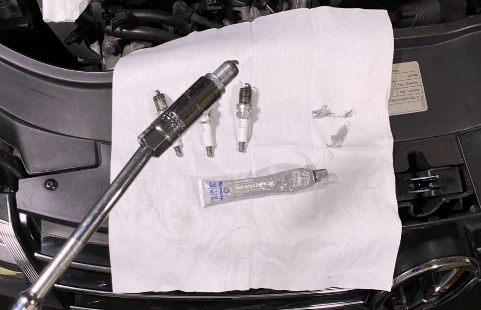
I recommend applying some anti-seize on the spark plugs’ threads before you drop them back in.
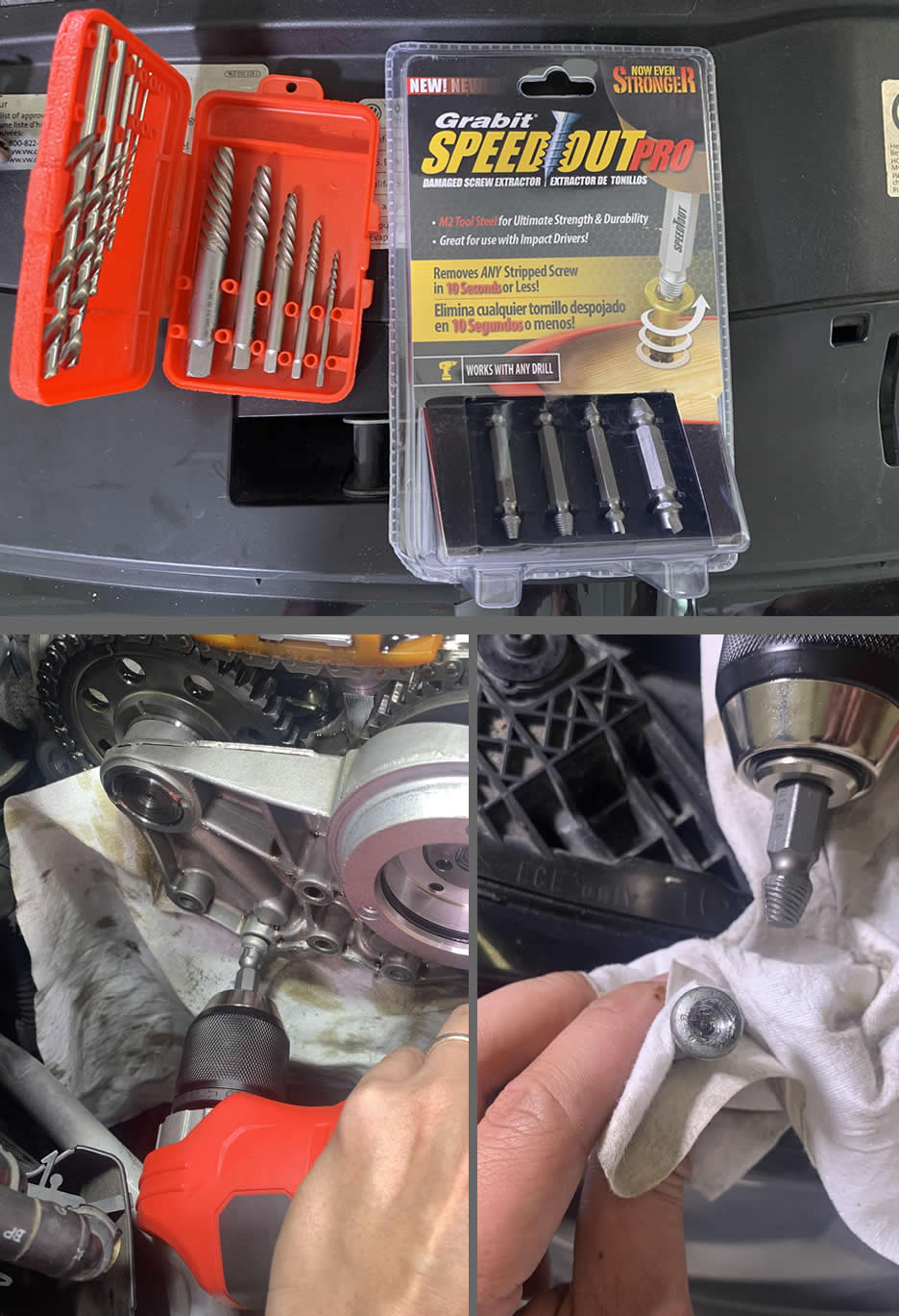
Stripped bolts!!
During the removal of the Cambridge Torx bolts, one of them was over-torqued by an impact driver before (thanks dealership’s “professional”!) and I stripped the bolt head while trying to remove it. What eventually worked for me after several trips to different hardware stores was the combination of Harbor Freight right-angle drill and Lowe’s Grabit speedout Pro kit
No crank!! P025C error code upon ignition!
If this was a few weeks long project, your battery might have depleted which leaves you with a bunch of error codes. The car may not even be able to start at all.
To rule out a dead battery, first try to open and close the driver door all the way for at least 5-10 times. This helps pump the fuel into the engine. Sometimes doing so gets rid of the P025C code and the car will start back up. The symptoms of this issue are long cranking noise upon ignition, engine sputtering but never finishes.
If your car’s battery is completely dead, you will hear some clacking noise followed by a total shutdown. You might lose power steering for awhile even after replacing the new battery or jump starting the car. In my case, my steering angle sensor was not responding at all, there was no communcation signal between the steering wheel and the ECU. I had to drive around the back road for thirty minutes to get the battery fully charged, let it sit overnight and the next morning all problems cleared up.
Well, I guess that’s all I have for now. I’ll add more to this section if something comes up in the comments. Best of luck on your repair!
I just conpleted the timing chain upper and lower and I replaced the lower cover but I believe that the new cover is rubbing on the crankshaft sprocket and causing a whining noise like a supercharger all throughout rev range
Thank you! No way I could have done this job without your guide. Starting the car up for the first time was scary but she fired right up. Saved me thousands and now I’m confident in the quality of the parts.
Thank you for putting the time in this post. Sometimes YouTube videos don’t catch all.
UPDATE
I went back and removed all guides to basically start over and realized all my problems were due to my inverting the upper guide for the balance shaft chain. I had it holding the chain “up” instead of the correct position pushing the chain down, creating too much chain tension.
Correcting this allowed me to install the new replacement chain and I even found the lower tensioner was able to be installed without any issue. Also, the new upper tensioner had plenty of room to be installed without modding the adjacent guide.
My bad!
The photos in this guide are essential to follow closely and failing to do so can be catastrophic.
Thank you again Paul for this fantastic, detailed repair tutorial.
That was one hell of a riddle for sure, I’m very glad you found the culprit!
Great guide on this repair from Hell!😆
I am experiencing an interference issue with the new updated upper tensioner that no one else has mentioned having (2012 GTI)
The adjacent lower balance shaft chain guide is in the way. About 3/16 inch of the top of the pivoting guide pushed by the lower tensioner is located where the new upper tensioner needs to go.
The only way I could get the new upper tensioner in was to saw off the very tip of this tensioner.
BTW, I was unhappy with the initial tension of the balance shaft chain simply trying to install the first upper tensioner. It made the chain as tight as a drum and it was difficult to get the mounting bolts in, so I went and reused the original 123K miles chain.
Also BTW, I would NEVER had attempted to replace this balance shaft chain and guides had I known what a nightmare it was going to be. Trying to get the lower tensioner threads caught was nearly impossible without first removing the guide it pushes and them manhandling everything back after just catching a few threads on the tensioner.
Plus, trying to confirm that the yellow arrow was aligned with the two marked teeth on the upper right drive gear was another nightmare as it is nearly impossible to see from above or below the car.
I wish I’d had some warning.
So, am I the ONLY ONE who had to modify the lower left balance shaft chain guide in order to be able to install the updated upper tensioner???
Thank-you very much for this tutorial. It was incredibly helpful. Everything went back together perfectly. I did go with the turbo muffler delete as well. I used FCP Euro for my parts. They prepared the repair kit with everything I needed. I purchased an Amazon VW 2.0T timing chain tool kit which worked good as well.
Thanks again for taking the time to help us complete this challenging task!!
David
Thank you so much for putting this together. Lots of work you put into this, I really appreciate it. I got stuck after taking out the oil pump tensioner, the first chain worn come off. I don’t seem to have enough slack on the change to get it off the sprocket. Do you have any suggestions?
Thank you
You can temporarily remove the crankshaft bolt and its spacer to see if that helps.
Thank you so much. I just did a timing chain job on my mk7 golf R, and your information was absolutely crucial. I really appreciated the explanations, and the hand-holding!
You’re welcome, I’m glad it was helpful!
I can’t thank you enough for this! I bought a used GTI knowing that these engines have a tendency towards self destruction, but with your instructions I managed to do the job myself! I also really appreciate the recommendation to get a new timing chain cover. I wouldn’t have done that, but for a change I decided to listen, and I think it was a wise call. Anyway, I can’t thank you enough for this. I’d buy you a beer if I could!
I’m so glad you found the article helpful!
Thank you SO MUCH for posting this! I was on the fence about replacing the timing belt on a 2014 Jetta 1.8t (EA888), but then I read through this. The step-by-step with torque settings and everything, with nothing left out for a Jetta (like the engine mount) is SO helpful! I like the advice to use zip ties to keep tension on the chain. Great idea! I bought all the parts I needed after reading this page completely, and then the site went down! It came back up last Saturday morning, just before I started the job. I have 6 videos queued on YouTube on replacing a EA888 timing chain, but none of them are as useful as this post!!!
Paul,
Would I be okay to use this with my Gen 1 (presumably… its a 2010)? So far its been very similar with some slight differences in the initial steps.