Check out this super nerdy project by Abhishek Singh, the creator of Peeqo bot!
Abhishek used 3D print tech, Raspberry pi and many other geeky magic stuffs to make a bot that can interact using funny GIF memes. Sweet heaven!
Peeqo – the GIF Bot
Peeqo is a personal desktop robotic assistant who expresses himself through GIFs. Think of him as the love child of Amazon Echo and a Disney character. He has a conversational UI, so he responds to voice commands but answers only through GIFs.
This was quite a complex build as it involved several different skill sets and disciplines. I’ve tried breaking it down and have provided the files, code and purchase links to the parts wherever needed.
Also I’m open sourcing this whole thing, so if you would like to connect, ask questions, help with development or contribute in any way head over to http://peeqo.com/
Initial Paper Sketches
I began by doing several rough sketches on paper. I always like starting on paper to get the ideas flowing. The only real constraint I had at this stage was the size of the bot. Since he would be sitting on my desk he needed to be fairly compact and small.
Initial 3D Modeled designs
After arriving at a sketch I liked, I went into Autodesk Fusion 360 and modeled it out.
You can see an evolution of some of the sketches but also an evolution of my skills as this was the first time I was ever using a 3D CAD program. Though I liked the form factor of some, I realized I needed to consider the movement I wanted my bot to have and this ofcourse was a major design constraint as well.
Tennis Ball Prototype to Test Desired Movement
To demo the movement I wanted, I cut a tennis ball at an angle, and using some blue foam, a wooden rod and a drill bit modeled this prototype.
These were the movements I wanted as they would be able to convey all kinds of expressions (happy, sad, curious, excited etc) basically akin to the human neck. While creating 4 degrees of movement was achievable, figuring out a mechanism to create 6 degrees of movement was quite hard.
Modelling Various Mechanisms
I tried to sketch, model and visualize different mechanisms that would give me the 6 degrees of movement that I wanted. The one above is just one of several. All had some issues, either in not leaving enough space for the other components to fit inside the bot or requiring custom gears and parts to be designed.
Eventually I came across the Stewart Platform and realized I could make it work for me.
Final Design
The stewart platform mechanism then began to govern my final design. I decided to place the head on the top of the platform and use the base of the platform to lay out some of the components and the 6 servos.
Since the stewart platform has empty space right down its central axis that would work as the spine of my robot allowing me to run wires from the base to the head. It was the perfect combo of movement with minimal real estate usage. The stewart platform eventually dictated Peeqo’s cylindrical shape.
Obviously I couldn’t have a rigid body or an exposed exoskeleton, so I created a flexible covering that could bend with the movements.
Final Design ready for printing
This was the final design. It was just a little over 8 inches in height which I was quite pleased with. I spent most time ensuring everything was correct so that there would be no need to reprint the parts. Though I did model the rods and joints of the stewart platform in CAD, I couldn’t get all 6 joints to work so I just hoped my measurements were correct and there was some bug in the program. I was correct!
This is the final design (.IGS file) – https://github.com/shekit/peeqo-robot/tree/master/3d_design
You can view the file by following this link. If you have Autodesk Fusion 360 then you can also download and manipulate it
3D printing on Projet 7000
I was working with very tight tolerances so I got the parts printed using a ultra high definition Projet 7000 printer. Did it at the awesome LaGuardia Studio in New York.
3D printed parts fresh out of the printer
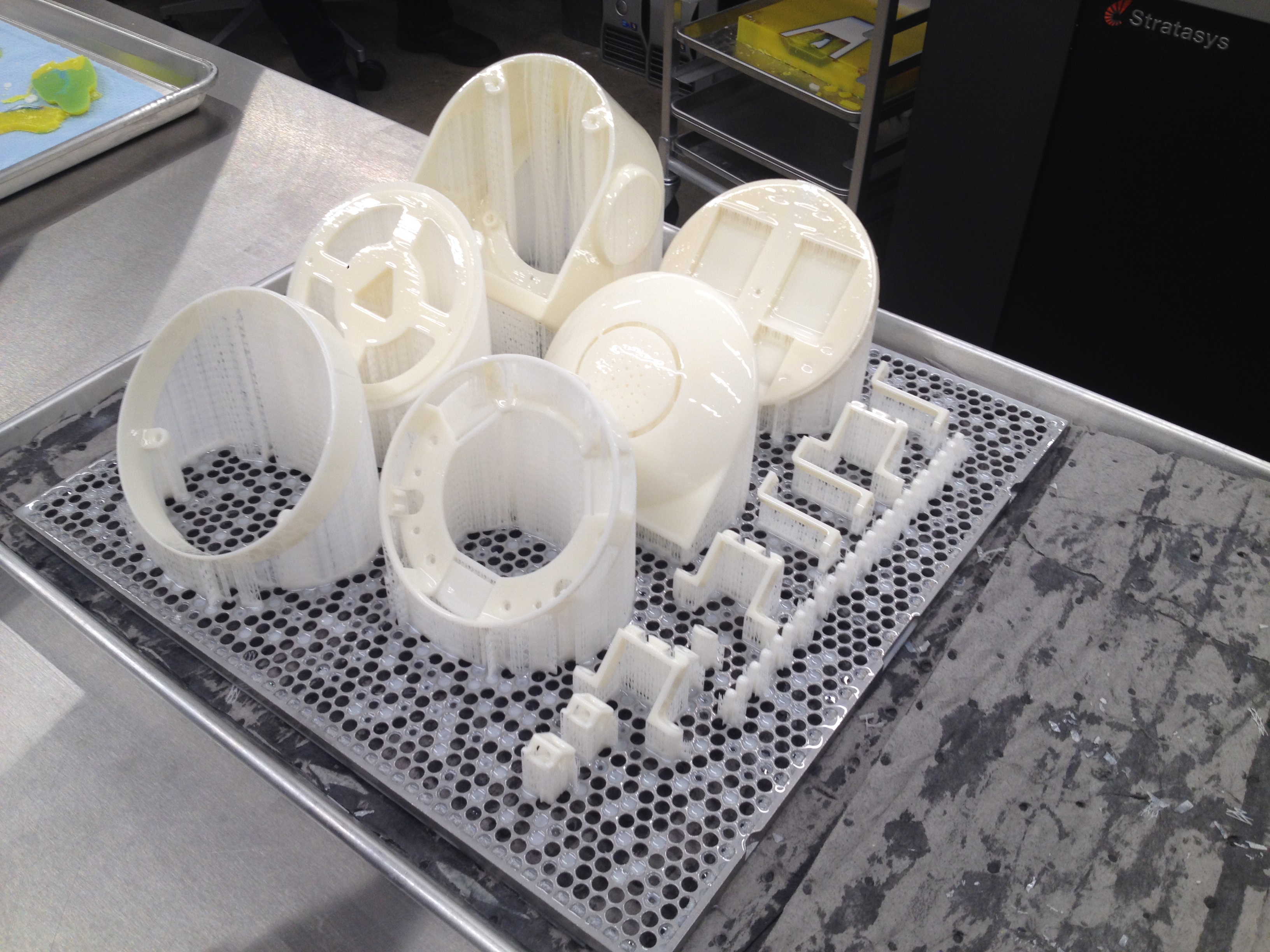
You can find all the STL files that you need to print these parts on my github. If you want to modify the design then I have provided a link to the CAD file a couple of images above.
STL files – https://github.com/shekit/peeqo-robot/tree/master/stl_files
Etching Custom Circuit Boards
I used 2oz copper boards and made 10 PCBs in totals. I needed them to be small to fit and 2oz copper boards allowed me to make thinner traces and still allow enough current to pass through. The steps were:
1) Design schematic and board design in Eagle (files provided below)
2) Print onto transfer paper
3) Toner transfer on to 2oz copper board
4) Acid etch using 1 part Hydrogen Peroxide, 1 part Muriatic Acid
5) Tin the boards using liquid Tin to help with soldering
6) Populate the boards with the components
7) Place the boards in the reflow oven
You can find the Eagle files(schematic and board layouts) for all the circuits here.
3 PCBs for Servo control – one also was the power inlet
1 PCB for connecting the wires from the base to the head
1 PCB as a breakout for the Arduino Minis
3 PCBS for the mics(2 in the ears, one facing forward)
1 PCB for power distribution and mic control in the head1 PCB for the Neopixel ring
I also had to make a library for some of the parts I had ordered which are in the github as well. I have included a parts list and links to the parts later on.
Saving Space – Pointing RPi USB Port Up
One of the biggest challenges was trying to fit all the parts into the small space. This meant every millimeter counted and at every step I tried to save some space. One of those steps was with the Raspberry Pi.
I desoldered the ethernet adapter and the USB ports on the Pi 3. I then purchased vertical usb ports from digikey and soldered them in place. I had to add some extension headers and 90˚ headers so that the vertical ports lined up with the existing pads on the pi. This helped save valuable real estate as the USB chords could now plug in from the top reducing the overall length needed.
Hacking a USB SoundCard so Peeqo Can Hear
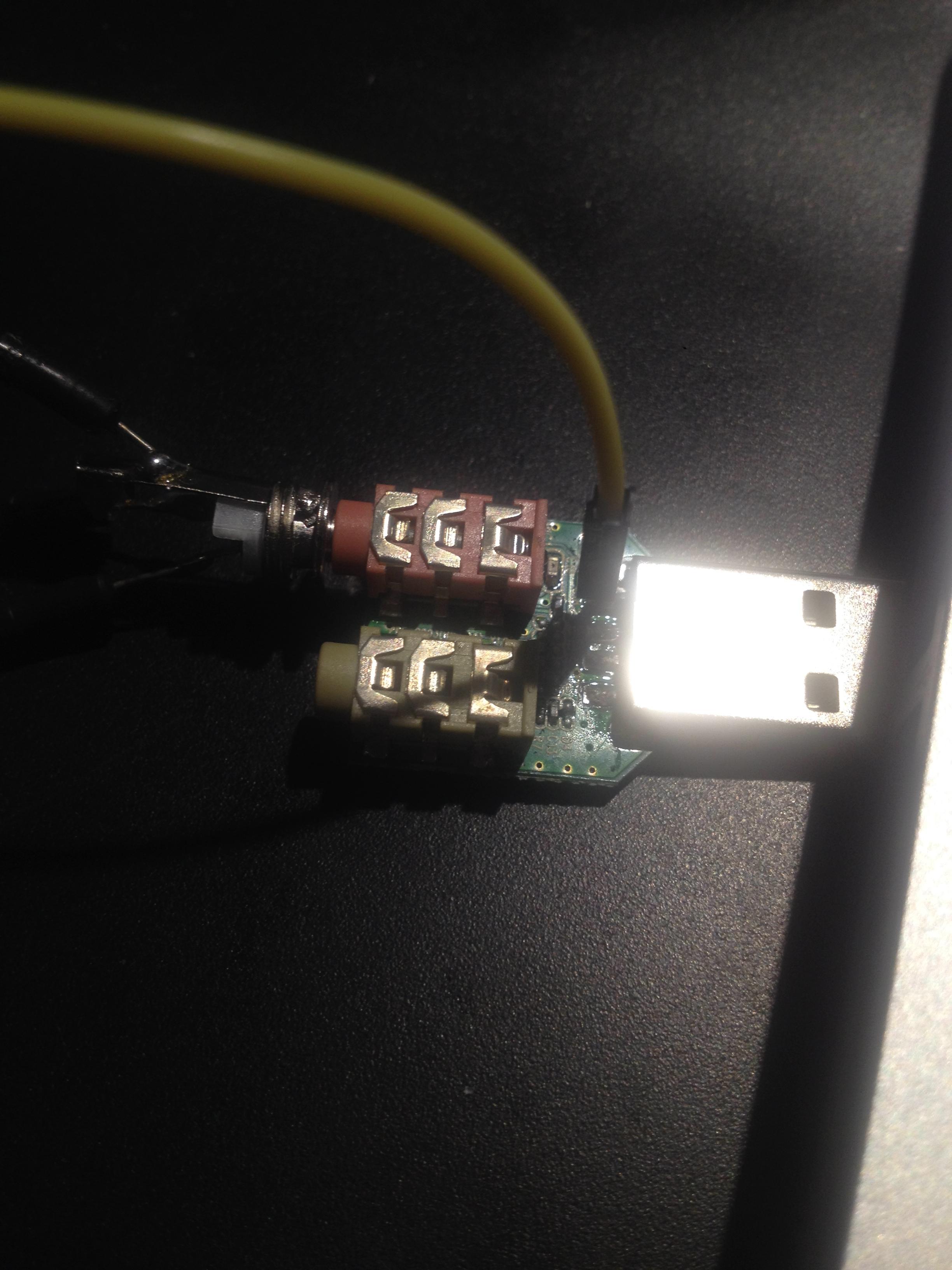
Since I was designing 4 custom mic boards which would allow Peeqo to hear, I needed a way to read the input from them using the Pi. The easiest way I figured to do this was to use a USB soundcard that would plug into one of the Pi’s USB ports.
1) I purchased a USB soundcard (http://amzn . to/2fV8fJO)
2) Removed the outer plastic casing
3) Jumped a wire(the yellow one) from the USB power to power my mics. I used Knowles MEMS mics purchased from Digikey. You’ll find a link to my digikey parts list later.
4) I soldered the output wire from my mic board to a regular AUX cable that then plugged into the soundcard.
Peeqo’s Body
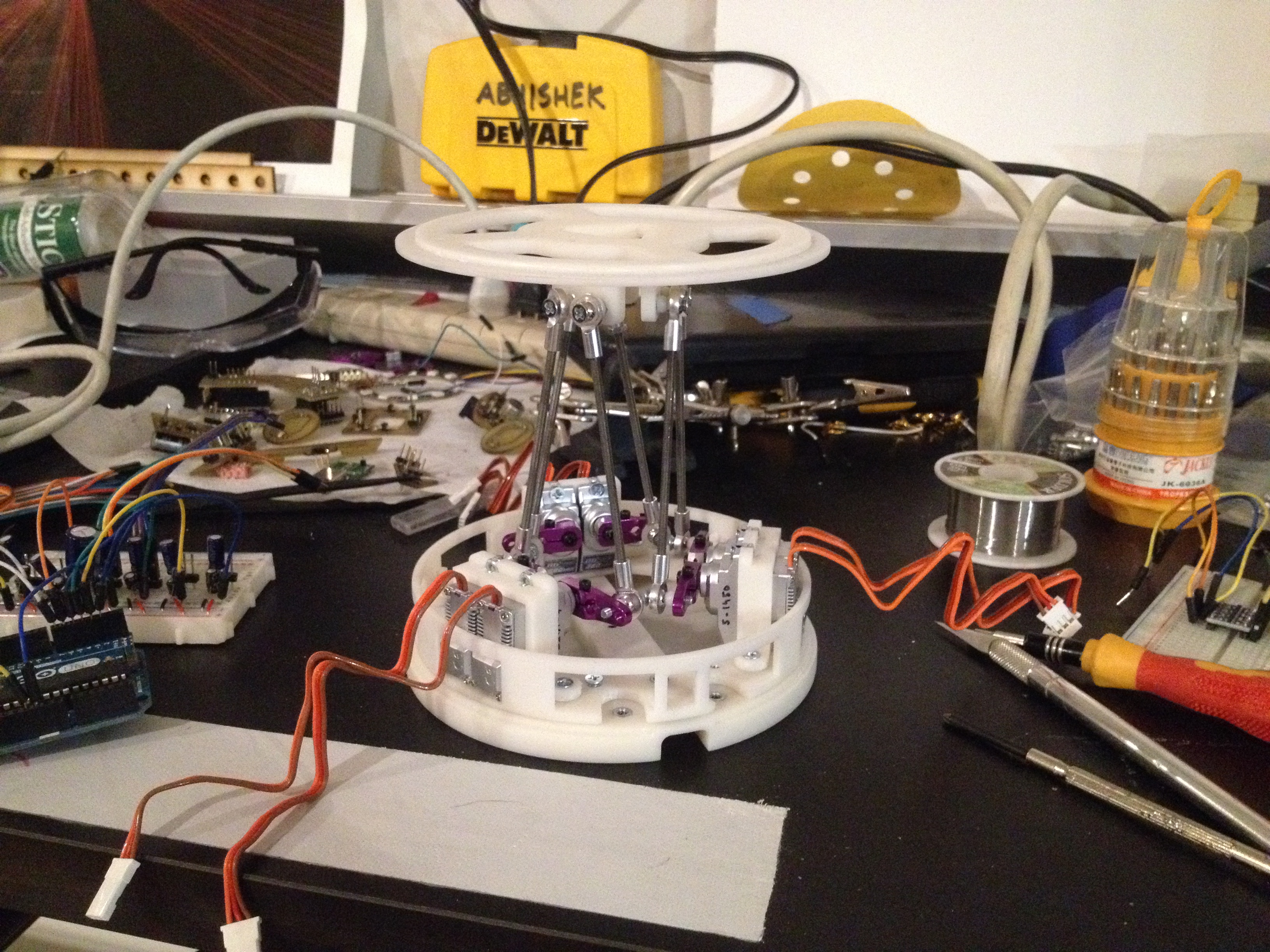
This is what the platform looked like.
As you can see the central shaft is empty and I use this to run wires through this from the base to the head. The platform was also wrapped with a flexible fabric to both hide the inner parts and allow the robot to move.
The Assembly Process
Here’s a stop motion of the entire assembly process.
I designed him so that he can be assembled from the ground up and disassembled from the top down for easy access to troubleshoot. Some points to note:
1) I added some lead weights into the base to increase stability. This also reduced the amount of material that needed to be used for 3D printing
2) I stitched a Spandex covering for the exposed body of the stewart platform section. This gave Peeqo the flexibility to move and also an organic feel as well.
3) For the spherical top to attach to the head, I used Neodynium magnets instead of screws. The magnets are strong enough to hold it together, no external screw holes are seen and its also easy to remove the top to access the electronics.
4) For the parts that did need to be screwed together, I created insets in the 3D CAD file. I then used Epoxy to glue Hex Nuts into these insets which then worked as threaded inserts.
5) I also used magnets to snap some of the circuits in place and to snap the front screen in. The less screws the better for parts that aren’t providing structural support.
6) He also has an LED ring on the top of his head which serves as a notification light.
7) I also used the shortest USB cables and HDMI cables that I could find to save on space. All are linked to later in the parts list.
LED Notifications
I 3D printed this as two parts. The translucent material was printed so it would let the LEDs shine through. It was then just press fit into the head and the LED ring was placed right underneath it.
Programming – Brain Surgery
I built peeqo up so that I could easily get back in and troubleshoot or program if needed. The upward pointing USB ports definitely help with this as its easy to plug in a keyboard and mouse and do some debugging.
1) Peeqo’s brain is a Raspberry Pi 3.
2) He uses 2 Arduino Mini’s to control the servos for movements and LED’s for notifications.
3) He has 4 Mics, one in each ear and two facing forward.
4) He has a Camera (http://amzn . to/2gjbvzB) at his chest and can take pictures but this ends up being a little slow on the Pi. Was hoping he could follow and track faces. Perhaps with some further optimization that would be possible.
5) He has a USB speaker that is powered by the Pi
Is that it?
There was a lot of programming that needed to be done as well to actually bring him to life. I’ve included a link to all the code below.
1) Electron
I used electron to write a native app that would run on the Pi and is the main program running on the bot. So using HTML, CSS and JS
Electron App – https://github.com/shekit/peeqo-robot/tree/master/code/electron
2) Node
I wrote a server in Node, this was used to do some testing and debugging using socket connections. It would also possibly be a place where he could begin storing preferences:
Node Server – https://github.com/shekit/peeqo-robot/tree/master/code/server
3) Arduino
There are 2 arduinos, one controls the LED notification ring (using Neopixels) on the top of the head and one controls the servos. I possibly could have done it with one but since Neopixels don’t work well with Servos on the same arduino I split them up.
Arduino Code – https://github.com/shekit/peeqo-robot/tree/master/code/arduino
The RPi communicates with the Arduinos using i2C.
4) Voice Recognition
I used a combination of Google Speech Api and Api.ai for the speech detection and response part. Google speech detects the keyword ‘Peeqo’ and Api.ai responds to the query
I am thinking of moving this entirely to Amazon Lex or Google Cloud Speech Api now.
Keeping me in Check
I also wrote a chrome extension so I can use him to keep track of my productivity and motivate me to stay off social media when I should be working. So once I tell him to block a certain site for me and I attempt to access that site, he lets his displeasure be known.
Here is the chrome extension code: https://github.com/shekit/peeqo-robot/tree/master/code/chrome_extension
Playing Music
I’m still working on adding robotic sounds that would add to communication of his mood/expression but until then he’s a full fledged entertainment system. So ask for a song and he’ll play it from Spotify and sway to it as well.
Parts List – You got it
1) Mechanism & Assembly:
- Servos (x6)
- Servo Arms (I cut these in half x6)
- McMaster-Carr (Everything is Metric)
- Aliexpress
- Magnets
2) Circuit Components:
3) Screen:
4) Processing & Cables:
Ah this post is almost over!
That’s All Folks
And remember if you want to connect, have questions or get stuck somewhere head over to the site and drop me a mail @ [email protected].